This page is an old, at 1/17.
In 12/16, I wrote a NEW explanation of using 1-Wire temperature sensing chips like the DS18B20 with an Arduino (or ESP8266, Teensy, etc!). Read that FIRST if you are new to the topic
However, for now, I am leaving the rest of this page here, in case you have read everything else, and are still seeking that "Eureka" moment which WILL come, if you just bang your head against the wall long enough, and come at it again and again from differnt angles!
This page could a little editing, and I hope you'll forgive the shortcomings in what follows. I still think, though that there is Good Stuff here for you. Worth what you've paid me for it, at least!
Please do not be put off by the extent of what follows. Using the 1-Wire chips on an Arduino via the Controller is quite straightforward, simple. This has got long because of my fuzzy mind, and because I am trying to tell you all that is going on, to make it possible for you to adapt anything that you wish to.
Sadly the creator of the device this page discusses passed away a few years ago, after tremendous contributions to hobbyist (and higher) electronics. However, many of his web pages are being maintained. Some of his devices are already on the market from authorized sources, and, GREAT NEWS!... there is a chance that the OneWireController will come back to the market before too long. If you would want to buy one, I would be grateful to hear from you, to help me in my campaign to convince the relevant people that it will be worth the trouble they will need to go to on all our behalves. (No, your "interest" won't be treated as a firm offer to buy.)
In passing... you may be interested in my more general information about connecting devices, e.g. Arduinos, Windows PC, etc, via serial links, including RS-232.
This page is browser friendly, by the way. Make your browser's window less wide than your whole screen and you will find the narrower columns much easier to read.
I am a long time fan of the Dallas "1-Wire" chips, which can (usually) be strung together into networks of sensors and actuators driven by a "master", either a full PC, or a microcontroller. When a number of 1-Wire chips are working together, the circuit is called a MicroLan.
I said "usually" a moment ago, because to make things simple (and inexpensive for you!) the 1-Wire chip controller that this article is built around does not support strings of 1-Wire chips. It will let you connect up to 7 1-Wire chips to it, so don't feel too hard done by!
Others have done good work in developing what you need to connect 1-Wire chips, and MicroLans to the Arduino. So why bother to read any more of this page?
Whereas those other efforts may give you access to the whole world of 1-Wire, I believe that another approach, the one outlined here, gives you "the best" of 1-Wire" with minimal hassle (relatively speaking!), minimal expense ($8), and minimal use of Arduino pins. For two (Arduino) pins, you can have access to seven 1-Wire chips, in whatever mix you choose. There are temperature sensing chips, reliable to 0.5 degree Celsius, and good over -10 to +85 degrees Celsius. There are counters... great little chips, with all sorts of uses. There are I/O chips, allowing you with one DS2408 to add 8 more "digital pins" to an Arduino. They can be inputs or outputs, or any mixture, and I think the inputs can "remember" if they have seen a momentary on (or off) at a time when the Arduino wasn't "looking". And then there are the modules built upon 1-Wire chips: barometers, humidity sensors, etc, etc.
For some projects the Anderson interface may have a "flaw" that is fatal... but that flaw will be irrelevant in many cases. To make the interface easy to use, a decision was taken. Each 1-Wire chip accessed via the interface must be connected to it via it's own wires. You cannot have several 1-Wire chips sharing wires "upstream" of the Anderson interface. But don't lose sight of the fact that through the interface you can have seven 1-Wire chips connected to your Arduino (or similar). Once you are happy with everything involved with working through the interface (a few notches up the learning curve!) you can always go further, and start "talking" to the same chips more directly. When you have those skills, you will be able to attach many chips to your master via just a pair of wires. The chips connect to that pair of wires like rungs on a ladder, each "rung" being one chip, and the stringers of the ladder being the two wires of the pair. The clever, clever thing about the 1-Wire protocol is that even though all of the chips are connected in parallel to the master, it can "talk" to them individually.
But! Back to THIS project... using the interface. In the code below I show you how to connect a Peter Anderson One Wire Controller ($8) to an Arduino, using just pin 0 (sorry... but yes, it "has" to be on the "special" serial-in-to-Arduino pin) and one other pin. That can be any pin. In what follows, I also show you how to attach, using just one Arduino pin (any pin), an LCD display by using the ModernDevice controller, itself based on another Peter Anderson pre-programmed PIC. (Once available from the long established, excellent https://www.wulfden.org, but it seems, alas, they stopped trading in 2017. I bought good things there, had good customer support.) The LCD controller, in an easily assembled kit, costs $9, but you also have to buy an LCD panel for it to control. (N.B.: the page the link above takes you to is headed "LCD Board", but on that page are ways to buy the board and the bits you need. Or an assembled board.)
(If, by the way, I've also done a more concise page with just How To Connect An LCD Panel to an Arduino, or any other source of a serial data stream.)
In summary....
The following shows you the 1-Wire Controller from Peter Anderson, without any 1-Wire device connected yet. Yes... it really is simple:
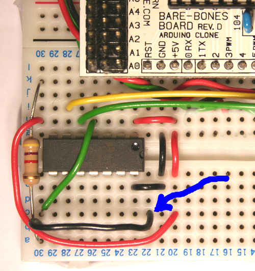
And that's just about it! You don't need to put anything on unused inputs to the 1-Wire controller chip. For the first demo program below, if you choose to give it a try, do not connect any 1-Wire chips to the controller. For the second program below, connect a DS1820 as follows...
Here are the details of which pin is which on the DS1820...
The DS1820's middle leg goes to pin 13 ("channel 0") of the 1- Wire controller. This is the 1-Wire data line.
The DS1820's leg marked "See text" should be attached to the 5v line shared by the components in this application. Not all 1-Wire chips have a pin like this, to be connected to a source of 5v. This is why the connection to 5v is not shown in the first diagram. It is actually possible to run a DS1820 without this connection, using "parasitic power", but it works better with one. (For parasitic power, connect this pin to ground (zero volts))
And the DS1820's "1-Wire 0v" should be attached to zero volts on the Arduino.
Just after this little table of further contents....
a) "Program 1" which makes a limited test that the Arduino, 1-Wire Controller and LCD display controller are "talking" nicely to one another. You don't really need it! It should just generate "255<cr><lf>" over and over again, reporting that the 1-Wire controller sends out.....
.... when it is sent the "R0" (that's "Read channel zero") command.
Further down the page....
b) Click here to go straight to "Program 2". That repeatedly reads a temperature sensor, and reports the answer in degrees Celsius. THIS is what you want, if you just want to get on with using the thing!
c) "Scraps"... half finished "stuff" relating to this project. Only for the really ken or curious!
d) Page footer, with "how to contact author", etc.
Program 1 is just to test a few elements of what we are building towards. It is "running successfully" if you see....
<nd>255<LF><CR><nd>255<LF><CR><nd>....
Appearing again and again on your LCD display. You may find that sometimes the output seems to stall for a moment. It is probably still arising, but is being "printed" "off the edge" of your LCD. The area the LCD controller uses can be made to match the area your LCD has, but that is not essential to this small test program.
The "<LF><CR>" says that the 1-Wire controller sent the codes for a Line Feed and a Carriage Return. The LCD controller is capable of line feeds and carriage returns, but for the purposes of this program I decided to replace them with the text.
If you get lots of "<nd>"s on the LCD, the program is saying that No Data was waiting in the T0 serial buffer when the program went to look.
If you are getting lots of "<nd>"s don't despair immediately. Try re-setting the 1-Wire controller chip first, by pulling it's pin 4 low, as explained a moment ago.
The reason that we get one ND between each 255LFCR is that we are using the absence of data to tell the Arduino that it is time to trigger another request for the 1-Wire controller to seek and report data.
Do study the remarks (comments) in the listing... more things are explained there....
#include <SoftwareSerial.h>
/*OneWireViaController1
ver 6Apr08

ADVANCED OVER the old one on pcHoward of Feb 08,
different name.

A skeleton program to test the following hardware..

Arduino connected to....
   a)ModernDevice/ Peter Anderson LCD controller
   b)Peter Anderson 1-Wire controller.

The LCD panel requires one line FROM the Arduino. Which pin is used is
defined by txLCDPin. This program uses the Arduino SoftwareSerial
library so that this does not have to be pin 1. The serial port created
by the call of "SoftwareSerial" (a data type provided by the library
of the same name) is created to use the same input pin as the OTHER serial
port this program creates. This is okay, as the LCD will never need to
look for any input from the LCD to the Arduino, i.e. the receive half
of the LCD port will not be used.

The 1-Wire controller takes care of a lot of the messy stuff in 1-Wire for
you, rather like the LCD controller takes care of the messy stuff of driving
LCDs. You just send ASCII strings to the 1-Wire controller, and it returns
ASCII strings with information from the 1-Wire chips attached to the
controller. The data TO the 1-Wire controller goes out on the pin defined
by tx1Wpin. The data FROM the 1-Wire controller was... (and maybe someday
I can make this work)...to come into the Arduino on the pin defined by
rx1Wpin. For now it is going to come into the Arduino on pin 0, the
Arduino's built in receive serial port data pin.

N.B.: You will probably have to disconnect the wire between the 1-Wire
controller and the Arduino's Rx pin while uploading the program.
Failed uploads will be your clue that you have to do this. A normally
closed push button momentary switch is worth it's weight in gold for dealing
with this nuisance.

In this form, the program will not read anything USEFUL from the 1-Wire
controller. It merely sends an "R0" request to it, and, once you have
everything running properly, reports the "255"<carriage return><linefeed>
which the 1-Wire controller will respond with, if nothing is connected to
it's channel 0. Before each "255" report, there will be a "No Data"
report.

How to connect useful things to channel 0 and the other channels, and how
to command them to determine a temperature or something, and report back
what they have sensed, are matters we get to in the next program. The program here is the "backbone" of that "next" program. It also checks that
certain facilities are in working order, before taking the development
of this project farther. Does the LCD panel work? Can we send commands
to the 1-Wire controller? Can we "see" things it sends back?  */


/*You can change all four of the following, just don't use 0 or 1 for any
    of them.
  Some of the "data lines" we are setting up are not used by the program
    for the jobs the lines names would imply they would be used for...
    but SOMETHING was needed to supply the parameters of the declarations
    of the objects myLCDSerial and my1WSerial.    */

#define txLCDPin 12 //no ; after #defines, remember
#define rx1WPin 10
#define tx1WPin 8

#define LEDpin 13 //A non essential "winker" to tell you the program
   //is at least going around it's loop, not stuck somewhere within it.

/*Next set up two software serial ports. Note that we won't be using
  the data-from-LCD-controller at all, and that we will "harvest" the
  data from the 1-Wire controller via the Arduino's "built in" serial
  port, pin 0, not via the receive channel of my1WSerial.  */

SoftwareSerial myLCDSerial =  SoftwareSerial(rx1WPin, txLCDPin);
SoftwareSerial my1WSerial =  SoftwareSerial(rx1WPin, tx1WPin);

char c;/*Data from the 1-Wire controller passes, one byte at a time
   to the rest of the program through "c".  */

//Establish the messages which will appear if "awkward" data come in....
char* sMyStr[] = {"<nd>","<.>","<QM>","<LF>","<CR>","str5"};/*Don't worry about this...
    It is a minor, peripheral issue.
    Use sMyStr[0] to access the first string. (Not sMyStr[1]) */
int iMsg; //Part of same

/*==========================*/
void setup()
{
pinMode(LEDpin, OUTPUT);

pinMode(rx1WPin, INPUT);
pinMode(txLCDPin, OUTPUT);
pinMode(tx1WPin, OUTPUT);

myLCDSerial.begin(9600);
my1WSerial.begin(9600);/*Not currently used to read FROM,
   but it IS used to write TO the 1-Wire controller.
   A Read-if-something-sent-soon-enough routine for
   SoftwareSerial would be very useful! But I haven't
   found/ written it yet. */
Serial.begin(9600);//Set for 9600 comms with 1-Wire controller
myLCDSerial.print("?f");//Clear LCD screen
delay(200); //give 1-Wire controller time to settle.
Serial.flush();//clean out any "stuff" that has accumulated, say
   //during programming of Arduino
}

/*==========================*/
void loop()
{
digitalWrite(LEDpin, HIGH);//So user can "see" how things are going.
iMsg=0;//Fake a call to charToStr... prepare way for "print it"
   //If no data coming in, the iMsg will still hold 0 when we get
   //  to the "print it" part.

if (Serial.available()==0) {
  /*No data waiting. Instruct 1-Wire Controller to send some...
    Even with no sensor on the channel, the controller can still
    TRY to read the channel.*/
   my1WSerial.print("R0");
   delay(1200);//Give time for stream of data to start towards Arduino
   }
   else
   {
   c=Serial.read();
   iMsg=charToString(c);
   delay(10);};

//So- we've collected a datum, if one's available. Now...

digitalWrite(LEDpin, LOW);//Change state of LED, so we can see where
    //program's got to.

/*In a moment we are going to print something. If it is
printable ASCII, and not the LCD's escape character, we will
just print what's in the variable "c".
All of the fuss... the call a moment ago to charToString (which set
iMsg to 255 unless there was a special case to deal with), the if/else
below, the array "sMyStr".... is simply to cater for all
possible data.... some of which would not print "nicely" on the
LCD screen.*/

if (iMsg==255)
  {
  myLCDSerial.print(c);
  }
  else
  {
  myLCDSerial.print(sMyStr[iMsg]);
  }

delay(200);//Give LCD controller a moment to deal with what
     //it was just sent, before going on.
} //end of function "loop"

/*==========================*/
int charToString(char cLocal)
{
  /*Look for, deal with, some tedious possible special cases*/
int iReturn=255;
/*If the function returns 255, the message is "print what was in c, passed into
    cLocal inside this function. If it returns something else, the message is
    "Use the string of that index from your array sMyStr of strings"*/

   if ((cLocal<32) || (cLocal>126)) {iReturn =1;};//Replace unprintable ASCII with "<.>"
        //Note that specific values will cause iReturn to change again, further down.
   if (cLocal=='?') {iReturn =2;};// '?' is the LCD controller's Escape code.... if it
        //is sent to controller, result will be unsatisfactory.
   if (cLocal==10) {iReturn=3;};//10: Linefeed character
   if (cLocal==13) {iReturn=4;};//13: Carriage return
return iReturn;
}
This "just does it"! It is an Arduino program to repeatedly ask a 1 Wire Controller to check a DS1820 connected it, read back the answer, and put it on the LCD display.
Stop press: I could have sworn this was working before I posted it. However, on 6 April 08, I found some problems... not least that somehow the temperature sensor on my proto-board had somehow become connected to a different pin of the 1-Wire controller. Arghh. The code has been extensively worked on, today, 7 April 08, and I again THINK it will work properly for you.... Sigh. It has certainly been tidied up considerably. There was a tiny error in the declaration of an array that caused a huge and very hard to fathom error... one that only became apparent as the temperature sensed dropped below zero. Many numb fingered hours passed finding that little darling. How to get sub-zero temperatures: Mix cold ice, salt and alcohol. Isopropyl alcohol (rubbing alcohol) is cheaper than vodka, but a word of warning: Do not lick your fingers if they have become covered in the salty isopropyl.... yuck, yuck, yuck, I can assure you.
Once in a while, if you start the system carelessly, you may find that you have to reset the Arduino, or the LCD controller, or the 1-Wire controller, but normally, they all start "playing nicely". When the whole, finished, system was give a power cycle, it started up without any extra resets.
/*OneWireViaController2
ver 7Apr08

#include <SoftwareSerial.h>

ADVANCED OVER the old one on pcHoward of Feb 08,
different name.

iFrmSerialCRLF() could perhaps be made more elegant,
and/or complete... but "works" as it is.

A skeleton program to test the following hardware..

Arduino connected to....
   a)ModernDevice/ Peter Anderson LCD controller
   b)Peter Anderson 1-Wire controller, itself connected to a DS1820
      family temperature sensor on channel 0... pin 13 of the 1-Wire
      controller.

This program goes beyond the previous one by adding the reading of
a temperature sensor chip (DS1820 family)
attached to the 1-Wire controller on channel 0. The program is written
to make the process of obtaining a tture from the chip as clear as
possible. Later versions would be built to make the fetching of a tture
more convenient in the context of a bigger picture.

This really isn't as bad as it looks! The basic ideas are not complex,
the facilities exposed are useful. There were just some tedious details
which expanded the code somewhat along the way, mostly to do with
displaying the results in a human friendly way.

The LCD panel requires one line FROM the Arduino. Which pin is used is
defined by txLCDPin. This program uses the Arduino SoftwareSerial
library so that this does not have to be pin 1. The serial port set up
by the call of "SoftwareSerial" (a data type provided by the library
of the same name) is created to use the same input pin as the OTHER
software serial port this program creates. This is okay, as the LCD
will never need to send anything to the Arduino, i.e. the receive
channel of the LCD port will not be used.

The 1-Wire controller takes care of a lot of the messy 1-Wire stuff for
you, rather like the LCD controller takes care of the messy stuff of driving
LCDs. You just send ASCII strings to the 1-Wire controller, and it returns
ASCII strings with information from the 1-Wire chips attached to the
controller. The data TO the 1-Wire controller goes out on the pin defined
by tx1Wpin. The data FROM the 1-Wire controller was... (and maybe someday
I can make this work)...to come into the Arduino on the pin defined by
rx1Wpin. For now it is going to come into the Arduino on pin0, the
Arduino's built in receive serial port data pin.

N.B.: You will probably have to disconnect the wire between the 1-Wire
controller and the Arduino's Rx pin while uploading the program.
Failed uploads will be your clue that you have to do this. A normally
closed push button momentary switch is worth it's weight in gold for dealing
with this nuisance.

For more information on the wonders of 1-Wire, go to....

         https://www.arunet.co.uk/tkboyd/e1didx.htm

... but you don't need to go there to use 1-Wire by the methods used by
this program.

*/

/*You can change all four of the following, just don't use 0 or 1 for any
    of them.
  Some of the "data lines" we are setting up are not used by the program for
    the jobs the lines names would imply they would be used for...
    but SOMETHING was needed for the calls of SoftwareSerial that set
    up myLCDSerial and my1WSerial.    */

#define txLCDPin 12 //no ; after #defines, remember
#define rx1WPin 10
#define tx1WPin 8

#define LEDpin 13 //A non essential "winker" to tell you the program
   //is at least going around it's loop, not stuck somewhere within it.

/*Set up two software serial ports. Note that we won't be using
  the data-from-LCD-controller at all, and that we will "harvest" the
  data from the 1-Wire controller via the Arduino's "built in" serial
  port, pin 0, not via the receive channel of my1WSerial.  */

SoftwareSerial myLCDSerial =  SoftwareSerial(rx1WPin, txLCDPin);
SoftwareSerial my1WSerial =  SoftwareSerial(rx1WPin, tx1WPin);

char c;/*Data from the 1-Wire controller passes, one byte at a time
   to the rest of the program through "c".  */

int iDataWas[10];/*Declare thus for TEN elements, last being iDataWas[9]
         due to iDataWas[0] existing. The number in the declaration is
         the number of elements, NOT the index of the last element.*/
byte bNextDatum=0;

//Establish the messages which will appear if "awkward" data come in....
char* sMyStr[] = {"<nd>","<.>","<QM>","<LF>","<CR>","str5"};/*Don't worry about this...
    It is a minor, peripheral issue.
    Use sMyStr[0] to access the first string. (Not sMyStr[1]) */
int iMsg; //Part of same


/*++++++++++++++++++++++++++++++++++++++++++++++++++++++
"setup" and "loop" function declarations at end of code.
+++++++++++++++++++++++++++++++++++++++++++++++++++++++*/


/*+++++++++++++++++++++++++++++++++++*/
int iFrmSerialCRLF()
{
  /*Tries to read a byte... as a string of ASCII codes for
  the digits of the decimal representation of the byte from
  the serial buffer. Also checks the ASCIIs for the byte
  are followed by a CR (10) and a LF (13), in that order.

  =========== . . . . .
  ***All you have to know about iFrmSerialCRLF:

  To use it:
  1) Put 1-3 ASCII codes for 0-9, followed by
         a LF/CR pair (10, 13), in the array iDataWas.
         The 1-3 codes should "spell" something
         in the range 0-255 (incl).
  2) Set the global variable (slapped wrist)
         bNextDatum to the index of the first
         of the ASCII codes.
  3) Call iFrmSerialCRLF, and...
  4) You will get back
         a 16 bit number. The top 8 bits are an error code. If 0,
         there was no error, and the lower 8 bits are your number
         in binary.
         bNextDatum will be pointing at the first element past
         the CR.

  The routine can catch: Not valid numbers. Absence of LF or CR.

  =====

  This "little" routine has been a pain out of all proportion
  to its significance in the Grand Scheme of Things... and it
  also makes the program very non-portable... but at least its
  "badness" is well "wrapped" in the function. If your data
  arrives in a different format, you simply have to write your
  own iFrmSerialCRLF.

  Because the program NEEDS the serial BUFFER, even though we
  have moved what was in it to iDataWas before starting this
  routine, the Arduino's serial routines on pin 0 have to be
  used for receiving the data from the 1-Wire controller.
  Sorry. You can't move the serial input for this to a pin run
  by the SoftwareSerial library until that at least gets a way
  to look for incoming serial data without getting trapped in
  a "looking" loop forever if no data is being sent
  to the Arduino.

  The digits of the byte and a terminating CR/LF pair (in that
  order, 10/13) should already be available in the array before
  the routine is called, and bNextDatum should point to the first
  digit of the ASCII coded byte you are going to read.

  The byte should be in the array in decimal ASCII form, i.e.
  50,53,53,10,13 would be what the buffer would have for
  255.

  The function returns with the byte in the lower 8 bits of the
  returned value, and an error code in the upper 8 bits.
  If they are 0, the read was successful.

  This function is not yet perfect(?)... but it should "mostly"
  work! Some error conditions may not be tested for/ reported...
  but the framework for doing so is there. Please tell me if
  you spot problems!*/

  int iLErr =0;/*For error code, 0-255. 0 says "no error"
     Upon completion of the function, the error byte will
     be moved to the upper 8 bits of iLErr, and the data
     byte "married" to the error byte by putting it (data byte)
     in the lower 8 bits of the 16 bit word.

     Other error codes: See below. I won't promise that no code
        got used twice! Do let me know if you spot a double use.

     Crudely coded, "brute force". Could probably be improved.
     */
  int iLRet;//Using int to be sure characters in serial buffer do not
    //indicate a number greater than 255
  byte bLTmp1;
  byte bLTmp2;
  byte bLProg=0;//Tracks progress... we should first find 1,2 or 3 digits, then a CR,
     //then a linefeed. bLProg starts 0. When CR found, becomes 1.
     //(MAY not actually be necessary. Consider working at writing out.

//Routine should not be called without first checking that there is
//at least one datum in the serial buffer.
  iLRet=iDataWas[bNextDatum];bNextDatum++;
  bLTmp2=AsciiToNumber(iLRet);//Returns 255 if iLRet was not ASCII for a digit, i.e., 0-9

  if (bLTmp2==255)
    {iLErr=10;};//Err 10 says 1st byte from buffer not a digit

  iLRet=bLTmp2;//Start accumulation of value. Okay whether error seen or not.
                   //If there was no error, now has 1st digit in it.
  //Process second byte from buffer....

  if (iDataWas[bNextDatum]==-1) {iLErr=40;}
  if (iLErr==0) //iLErr==0 "A"
    {
    bLTmp1=iDataWas[bNextDatum];bNextDatum++;
    bLTmp2=AsciiToNumber(bLTmp1);
    if (bLTmp2==255) //bLTmp2==255 "B"
       {
       if (bLTmp1==10)
          {bLProg=1;
           iLErr=iTryToFinish();
          }
          else
          {iLErr=12;}//Err 12 says a non digit, non CR found after one digit
       }
      else // of bLTmp2==255 "B"
       {
       iLRet=(iLRet*10)+bLTmp2;//Have now fetched two digits.
       } //end of else of bLTmp2==255 "B"

  //Fetch and process 3rd byte....

      if (iDataWas[bNextDatum]==-1&&(bLProg==0)) {iLErr=42;}
      if ((iLErr==0)&&(bLProg==0)) //iLErr==0 "C"
    {//Have already picked up two digits. Is there a third?
      bLTmp1=iDataWas[bNextDatum];bNextDatum++;
      bLTmp2=AsciiToNumber(bLTmp1);
      if (bLTmp2==255) //bLTmp2==255 "D"
       {
       if (bLTmp1==10)
          {bLProg=1;
           iLErr=iTryToFinish();
          }
          else
          {iLErr=14;}//Err 14 says a non digit, non CR found after two digits
       }
      else // of bLTmp2==255 "D"
       {
       iLRet=(iLRet*10)+bLTmp2;//Have now fetched three digits.
             //(Will test later for >255)
       } //end of else of bLTmp2==255 "D"


      if ((iDataWas[bNextDatum]==-1)&&(bLProg==0)) {iLErr=44;}
      if ((iLErr==0)&&(bLProg==0)) //iLErr==0 "E"
    {//Have already picked up three digits. If next two bytes
     //are not 10, 13, something's wrong.
      bLTmp1=iDataWas[bNextDatum];bNextDatum++;
      if (bLTmp1!=10)
       {iLErr=60;}
       else
       {bLProg=1;};//May not be needed here, but MAY be needed elsewhere


      if ((iDataWas[bNextDatum]==-1)&&(bLProg==1)) {iLErr=46;}
      if ((iLErr==0)&&(bLProg==1)) //iLErr==0 "F"
    {//Have already picked up three digits and a CR (10). If next byte
     //is not 13, something's wrong.
      bLTmp1=iDataWas[bNextDatum];bNextDatum++;
      if (bLTmp1!=13){iLErr=60;}

           };// Ends "if" block for iLErr==0 "F".. there is no else clause
        };// Ends "if" block for iLErr==0 "E".. there is no else clause
      };// Ends "if" block for iLErr==0 "C".. there is no else clause
    };//Ends "if" block for iLErr==0 "A".. there is no else clause

  if (iLRet>255){iLErr=30;}//Err 30: Value spec'd by chars in serial buffer > 255

  if (iLErr!=0){iLRet=0;};/*Mostly: To be tidy. But essential when iLRet>255, or
        else value in "error" part of returned integer is corrupted by upper bits
        of iLRet*/

  iLErr=(iLErr*256)+iLRet;
  return iLErr; //Isn't merely returning error value... datum has been mixed into
     //a 16 bit number with the error value.
}

/*End of big routine iFrmSerialCRLF()
--------------------------------------------------------*/


/*+++++++++++++++++++++*/
int iTryToFinish ()
{
/*Called from iFrmSerialCRLF()*/

/*This function is named for what it does, not to indicate that it is
still on my "to do" list!

This finishes something in the  function iFrmSerialCRLF. That will
have built up a value, and encountered a 10 (CR). This fetches the
next byte, checks it is the expected 13 (LF), and return 0 if so,
error code otherwise.

There may be no point in having this in a separate routine....
  other than helping make iFrmSerialCRLF more readable  */

int iLErr=0;
byte bLTmp;

if (iDataWas[bNextDatum]==-1) {iLErr=50;}

bLTmp=iDataWas[bNextDatum];bNextDatum++;
if (bLTmp!=13){iLErr=52;};

return iLErr;
}

/*+++++++++++++++++++++++*/
byte AsciiToNumber (byte bConvert)
{
/*Called from iFrmSerialCRLF()*/

/*Pass this 53 and it will return 5...
... 53 is the ASCII for five.
Pass a value outside of the values for 0-9 and
   this will return 255*/
byte bLRet=255;//note: Init at 255 takes care of cases where
  //non digit value passed to routine
if ((bConvert>47) && (bConvert<58))
       {bLRet=bConvert-48;}
return bLRet;
}

/*+++++++++++++++++++++++++++++++++*/
void DegCToLCD(byte bTtureInBoyds)
/*Only needed by the "unnecessary" stuff to USE the data the DS1820 returned*/
{
/*Display on LCD, in deg C, the value in bTtureInBoyds
Getting this function JUST right if the tture experienced
by the DS1820 is negative (in degrees Celsius) was trickier than
you might have imagined! Should be right. "-0.5" is a special case.*/

byte bHalfDeg=0;
int iTmp;
//bTtureInBoyds=29; for debug
if (bTtureInBoyds==255)
  {myLCDSerial.print("err");}
else //Print value
  {bHalfDeg=bTtureInBoyds %2;
   iTmp=(bTtureInBoyds/2)-15;
   if ((iTmp<0)&&(bHalfDeg==1)){iTmp++;};
   if (bTtureInBoyds==29){myLCDSerial.print("-");};
     //Previous for very special case: -0.5
   myLCDSerial.print(iTmp);

   if (bHalfDeg==0)
        {myLCDSerial.print(".0");}
   else
        {myLCDSerial.print(".5");};
  };//end of else- print value
} // end of DegCToLCD

/*+++++++++++++++++++++++++++++++++++*/
void ByteToLCD(byte ByteToDisp)
{
/*Only needed by the "unnecessary" stuff to USE the data the DS1820 returned*/
/*Put ByteToDisp on the LCD. I.e. if
  "255" is to be displayed, send 50,53,53,
  (three calls of ByteToLCD) (ASCII for "2","5" and "5")*/
  myLCDSerial.print(ByteToDisp,DEC);
}

/*+++++++++++++++++++++++++++++++++++++++*/
byte bCvtDStoBoyds(byte hi, byte low)
{
/*Only needed by the "unnecessary" stuff to USE the data the DS1820 returned*/

/*Convert the two bytes returned from DS1820 tture chip into a
byte expressing the tture in "Boyds". see essay at....

https://sheepdogguides.com/arduino/asw1onew1.htm

... for more clarification of why "Boyds" are a good idea.

Half of a Celsius degree is one Boyd degree.

Zero degrees Boyd is -15 degrees C
   1 degree Boyd is -14.5 deg. C
  70 degrees Boyd is 20 degrees C... a warm "room temperature".

Function returns 255 if there was something wrong, it could not
calculate the tture in "Boyds".

Works for negative (in degrees C) ttures as well as for
positive ttures.

====

Using this "odd" scheme makes many things easier. If you want to
express a tture in more usual units, e.g. Fahrenheit or Celsius,
the "way to go" is to write a conversion function to call on an
underlying "Boyd" value just before displaying the result.

The two bytes passed in hi and low use the coding used by the Dallas
DS1820 chip: a 16 bit, 2's complement value for the number of HALF
degrees Celsius "seen" by the chip. E.g....

Tture        High byte    Low byte    Hex equiv
+85.0°C	     0000 0000    1010 1010   00AAh
+25.0°C      0000 0000    0011 0010   0032h
+0.5°C       0000 0000    0000 0001   0001h
 0.0°C       0000 0000    0000 0000   0000h
-0.5°C       1111 1111    1111 1111   FFFFh
-25.0°C      1111 1111    1100 1110   FFCEh
-55.0°C      1111 1111    1001 0010   FF92h

*/
int iAns;
iAns=((hi*256)+low)+30;
if (iAns<0) {iAns=255;};//Flag as "not valid Boyd" tture below 0 B (-15 deg. C)
if (iAns>254) {iAns=255;};// ditto, too high tture (112 deg C)
//The limitations of working with Boyds are more generous than the chip's
//"certified accurate to 0.5 deg" range: -10 deg C to + 85
if ((hi!=0)&&(hi!=255)) {iAns=255;};/*Only 0 and 255 valid for
                   high byte from DS chip*/
return iAns;
}

/*=================================*/
void setup()
{
pinMode(LEDpin, OUTPUT);

pinMode(rx1WPin, INPUT);
pinMode(txLCDPin, OUTPUT);
pinMode(tx1WPin, OUTPUT);

myLCDSerial.begin(9600);
my1WSerial.begin(9600);/*Not currently used to read FROM,
   but it IS used to write TO the 1-Wire controller.
   A Read-if-something-sent-soon-enough routine for
   SoftwareSerial would be very useful! But I haven't
   found/ written it yet. */
Serial.begin(9600);//Set for 9600 comms from 1-Wire controller
myLCDSerial.print("?G2x24");/*Tell controller the rows and columns of
    the LCD it is attached to. Yours may be different, of course.*/
myLCDSerial.print("?f");//Clear LCD screen
Serial.flush();/*Clean out any "stuff" that has accumulated, say
   during programming of the Arduino.*/
delay(200); /*give 1-Wire controller time to settle, and for
   flush to be completed.*/
}

/*=================================*/
void loop()
{
unsigned long ulStartWait;//Used for storing a reading from millis()
unsigned long ulWaitUntil;
byte bDSLow;//Low half of 16 bit word returned by Dallas (DS) chip
byte bDSHigh;
byte bTtureBoyds;
byte bErr;//A byte to hold an error flag. 0= no error.
int iTmp;
/*Loop has two parts. In the first, the 1-Wire controller is told to
ask the tture sensor to make a tture reading, and pass the "answer" to
the Arduino via the Arduino's dedicated, buffered, async serial line on
pin 0. Eventually, I hope to be able to move this work to another pin,
but the "behind the scenes" buffering of input, not available with
SoftwareSerial, is very helpful. And with SoftwareSerial's "read", if
no datum comes when the Arduino has been sent off to read, the program
will hang up. Sigh.

The second part of loop will display the tture read by the 1-Wire
controller on the LCD panel attached via ModernDevice LCD panel
controller, which is on txLCDPin.

Don't be confused by the fact that a "don't call the controller again
until 3 seconds have passed" mechanism starts in the first "half" of
the code for "loop" and ends in the second "half".*/

//Start by asking the controller to ask the chip to take a reading....
my1WSerial.print("P0W0ccS044");/*The 3 0's all specify that we are
  talking to channel 0 of the 1-Wire controller. These weird strings
  could be explained... I'll try to get to it later... but for now
  you only need to know that they ARE strings, and you'd only change
  the 0's, and only if you wanted to read a tture sensor on a different channel.
  The 1-Wire controller does not support more than one 1-Wire chip on each
  channel... quite restrictive, in 1-Wire terms, but simplifies things at
  not-too-great-a-cost, allowing many applications by means of the 1-Wire
  controller we are investigating.

  This command asks the 1-Wire controller to tell the DS1820 to take a reading.
  The answer will, for now, still be in the DS1820. Taking the reading can
  take up to a second, hence the 1200ms delay in a moment.*/

Serial.flush();/*clean out any "stuff" that has accumulated in the Arduino's
     "main", built in, async serial port's buffer of received bytes.*/

/*Begin timing the 3 seconds that are meant to elapse between calls to the
 1-Wire controller. Don't be confused by additional, shorter, delays inside
 the 3 second delay. I'm not certain that I've started this timer at
 the perfect point.*/

ulStartWait=millis();/*Determine the "time" now. This approach will "fail"
    at times when the milliseconds-since-start rolls over during the
    interval timed. Roll overs occur about every 9 hours.*/
ulWaitUntil=ulStartWait+3000;/*Could probably catch rollover problems, and
   maybe even deal with, here, simply...*/
/*The "wait until time is up" part of this is much farther along, near the
   end of the "loop" function. So far we've merely made a note of what
   the millis function will return when we're okay to go on.*/

delay(1200);/*To let chip do conversion. NEEDED in addition to the bigger,
   more complexly generated delay.*/

my1WSerial.print("P0W0ccW0be");/*Now tell the controller to tell the DS1820
   to send the reading from the chip to the 1-Wire controller. The reading
   entails two bytes of data.*/

delay(100);/*Program this adapted from thought 100 enough.. but that was for different
    host uController. The delays in this Arduino version may need tweaking.*/

my1WSerial.print("R0");/*Ask the controller to send the first datum to the Arduino. We
  send "R0" TO the 1-Wire controller, which commands to it to send a byte of the
  data already collected from the DS1820, currently in the 1-Wire Controller.
  The Arduino's serial input buffer will accept it and hold it for us until we are
  ready to process it in the Arduino. The byte is sent as ASCII, followed by a
  LF and CR. So, for instance, if the byte were 23, the 1-Wire controller would
  send: 50, 51, 10, 13. (Numbers in decimal).*/

delay(100);/*Program this adapted from thought 100 enough.. but that was for different
    host uController. The delays in this Arduino version may need tweaking. When the
    delays after an "R0" command were merely 50, the second datum didn't make it
    into the array iDataWas.*/

my1WSerial.print("R0");//Ask the controller to send the second datum to the Arduino

delay(100);

/*Next we will move the data from serial buffer to own scratchpad. In a different
version of program I tried to draw data directly from serial buffer, but I couldn't
get that to work for some reason.... probably errors in my logic. Moving the data
to the array, and using it from there has no particular virtue, and wastes space.
The scratchpad array (iDataWas[x]) has 10 elements. If the serial port's buffer
is exhausted before all ten elements of the array have been used, the extra
elements are filled with negative 1's. Valid data will always consist of two
records, each of 1-3 ASCII codes for a digit 0-9, then a LF (10) then a CR (13).
The program checks that the LF and CR are both present. It doesn't care what comes
after the second LF/CR pair, as long as all that went before was okay. But if it
encounters a -1 before seeing two complete records, it flags the error. The two
bytes you can generate from the two records, between them, indicate the
temperature (tture) seen by the sensor. For how the data is to be interpreted,
either reverse engineer the following code, or see the discussion on....

             https://sheepdogguides.com/arduino/asw1onew1.htm

... where you may also find updated versions of this program. (The code's version
is specified in it's second line.*/

for (byte c1=0;c1<10;c1++){iDataWas[c1]=Serial.read();};
/*The buffer will not always hold 10 "useful" bytes. When it doesn't
  no harm comes of putting -1 in the upper elements. (Serial.read returns -1
  if buffer empty.)*/

/*For debug...
for (byte c1=0;c1<10;c1++){myLCDSerial.print(iDataWas[c1],DEC);myLCDSerial.print(" ");};
delay(2000);
*/

/*Here begins the second part of "loop", which
    interprets and displays the data....*/

digitalWrite(LEDpin, LOW);//Change state of LED, so we can see
    //where program has got to. (A frill)

/*- - - - - - - - - -
  First look for two records in the array iDataWas[x], and if found
  transfer as bytes to bDSLow and bDSHigh. (If not, flag error in bErr.)
  End of this task is marked with further comment*/

bDSLow=0;//establish default value, in case of problem with read.

bNextDatum=0;

/* For debugging work...
iDataWas[0]=50;//Determines low byte
iDataWas[1]=53;//can be other than 0 or 255
iDataWas[2]=53;
iDataWas[3]=10;
iDataWas[4]=13;
iDataWas[5]=50;//48 is zero (50 is"2")
iDataWas[6]=53;//(53 is "5")
iDataWas[7]=53;
iDataWas[8]=10;
iDataWas[9]=13;
*/

if (iDataWas[bNextDatum]==-1) {
  //No data waiting.
   myLCDSerial.print("?fOdd.. buffer empty.");
   myLCDSerial.print("?nShouldn't have been.");
      // ?f clears LCD display, ?n should start new line
   delay(2000);
   bErr=80;
   }
   else
   {//Read first byte.... start of "Else clause RFB"
    iTmp=iFrmSerialCRLF();
    bErr=(iTmp & 0xFF00) / 256; //Extract the data and error codes from iTmp
    bDSLow=iTmp & 255;

    bDSHigh=255;//Establish default value, in case earlier error aborts read of
    //second byte.

    if (bErr==0){ //See if there was an error already. If not...
    //... read second string of ASCII for the second byte from the controller...
    if (iDataWas[bNextDatum]==-1){
         //No data waiting.
         myLCDSerial.print("?fOdd... buffer had");
         myLCDSerial.print("?nonly one record.");
         delay(2000);
         bErr=82;
         }
       else
        {
        iTmp=iFrmSerialCRLF();
        bErr=(iTmp & 0xFF00) / 256; //Extract the data and error codes from iTmp
        bDSHigh=(iTmp & 255);
        }
     } //End of... "if (bErr==0) //See if there..."
    }//.... end of "Else clause RFB"

/*This is where the "Look for two records in the array iDataWas[x]" task ends.
  We've either got two bytes of good data in bDSHigh and bDSLow, or we have
  something other than 0 in bErr.
     - - - - - - - - - - - - - - - - - - - - - - - - - */

/*Print the values. Remember that if bErr does not equal zero, the values in bDSHigh
     and bDSLow may be meaningless.
  The values won't mean much to a human, but will be helpful while debugging the
  routines which translate them to human-friendly results.*/

myLCDSerial.print("?fErr:");//?f does a "clear screen/home cursor"
ByteToLCD(bErr);

myLCDSerial.print(" Low:");
ByteToLCD(bDSLow);

myLCDSerial.print(" Hi:");
ByteToLCD(bDSHigh);

/*----------------------------------------------------------------
"That's it" as far as "working" the DS1820 via the 1-Wire controller.
(Apart from ensuring that another demand is not made of the controller
    too soon.)
From here to the "End of complicated" comment is just "unnecessary" stuff
which USES the raw bDSHigh/bDSLow data.*/

bTtureBoyds=bCvtDStoBoyds(bDSHigh,bDSLow);//See the routine

myLCDSerial.print("?y1?x00");/*Position cursor at start of 2nd line.
     Was having trouble with ?n (newline)...
     didn't work if I'd already printed 20 characters on 1st line.
     N.B.: 2 digits for x cmnd, 1 for y*/

myLCDSerial.print("Tture,deg.C:");
DegCToLCD(bTtureBoyds);
myLCDSerial.print("    ");//To deal with possibility of next line being shorter

/*End of complicated frill.
-------------------------------------------- */

/*Other stuff can be done here... as long as it doesn't access the "resting"
1-Wire controller, or upset the value in ulWaitUntil*/

//.. and now wait for rest of "wait" time which started earlier....
while ((millis()<ulWaitUntil)||(millis()<3000)){/*wait for time to pass... give 1-Wire time to do its thing*/};
   /*"or millis >429..." crude protection against caught-by-rollover
   This wait to give the chip time to take the reading.
   Max value returned by millis: 4,294,967,295.

   Current condition can, near a roll-over, give delays of up to 5.99 seconds...
   I think... What ulWaitUntil will be if it was set when millis was near the
   roll over was I haven't worked out carefully enough, nor the effect on
   the (millis()<ulWaitUntil) test....*/

}//end of "loop"
There you have it. I hope it is useful and interesting... the POLISHING of the "working" version took the best working hours of three days.
The DS1820 temperature sensor returns two bytes of data when you ask it to measure and report a temperature. That much I know, and am confident about.
But! Your "1820" may be either the 1820 I'm talking about, or a relative. The relatives don't always use the same scheme of translating the two bytes to a value in "normal" terms. And, even if I'm looking at the right data sheet as I set about the following, I know from past experience that I often get these things wrong, especially when dealing with negative numbers.
I'm going to give you all the facts first... bad luck... but then I'm going to propose an answer which I hope you'll find you are happy to "just use".
The datasheet tells me that the following temperatures will result in the following byte pairs....
Tture        High byte    Low byte    Hex equiv
+85.0°C	     0000 0000    1010 1010   00AAh
+25.0°C      0000 0000    0011 0010   0032h
+0.5°C       0000 0000    0000 0001   0001h
 0.0°C       0000 0000    0000 0000   0000h
-0.5°C       1111 1111    1111 1111   FFFFh
-25.0°C      1111 1111    1100 1110   FFCEh
-55.0°C      1111 1111    1001 0010   FF92h
The high bytes wastes 7 bits! It is either 00000000 or 11111111. It gives the SIGN of the temperature. One bit would have sufficed.
The low byte is the temperature in half-degrees-Celsius. So, 1 means half a degree above 0, 3 means 1- and- a- half degrees above zero, 80 means 40 degrees above zero. And so on.
So far, not too bad?
The tedious bit is that the temperatures are expressed in "2's complement", and this makes negative numbers a little weird. (There was a good reason for doing this, by the way!)
I've already explained about the state of the high byte. And what I've said about the representation of positive numbers is complete, even though it is in 2's complement. It is negative numbers which get a little tedious. To get the number you and I would find easiest from a 2's complement negative number, you...
1) Complement it: Change each 0 to a 1, and each 1 to a 0.
2) And then ADD "1"
(I put "add" in capitals to emphasize that you may have carrying to do. N.B.: The data from the 1-Wire chips is 16 bits long.... you "stick together" the two bytes, sign bit first. The spaces in my numbers below are just to make them more readable. And I am showing the numbers in binary, the way to go when doing 2's complement.)
So...
The table of examples shows us....
- 0.5 is shown with 1111 1111 1111 1111, and
-25.0 is shown with 1111 1111 1100 1110
The twos complement of the 1st is....
Start by simply complementing: 0000 0000 0000 0000...
Then add 1, result....
0000 0000 0000 0001...
"1". As before: "1" HALF degree Celsius.... BUT! You know it is NEGATIVE 0.5 degrees Celsius because you have done a 2's complement on it before arriving at 0.5
The twos complement of the 2nd is....
Start by simply complementing: 0000 0000 0011 0001...
Then add 1, result....
0000 0000 0011 0010...
"50". As before: "50" HALF Celsius degrees.
(You can also read these as follows.... First the top 15 bits: 0000 0000 0011 001 :25 Then the right hand most bit for the half degrees, in this case, 0: no halves.)
Well! That was all tedious enough, wasn't it?
I'm going to suggest the following.
To make working with temperature coming from DS1820s really easy in the rest of whatever program they are for I'm going to use "Degrees Boyd", abbreviation "B".
Zero degrees "B" is equivalent to -15 degrees Celsius.
1 degrees B is -14.5 degrees Celsius
16 degrees B is -7 degrees C. (8 degrees warmer than 0 degrees B)
254 degrees B is +112 degrees C
If you adopt my "crazy" scheme, you get a nice simple unsigned 8 bit number to store any temperature in the device's accurate range to it's full possible accuracy. An no further hassle!
Of course, if you want to do something different, you can. I've given you all the information on the fundamental data.
If you want to display a temperature in human-familiar terms, it is quite easy to set up little functions to convert from Boyds to Fahrenheit or Celsius, to be called just as the data goes "out" of the computer. (There's a suitable routine for displaying a temperature in Celsius degrees (DegCToLCD) in "Program 2" above. If you write your own, watch out for -0.5!) Within the computer, take my word for it, you'll like Boyds! So, for instance, you want to turn the heat on at 14.5 degrees C? That's simply a matter of turning it on at 29 degrees B.
I've also put a data-from-the-1Wire-controller to Boyds function into "Program 2". The function is called bCvtDStoBoyds
The following was harvested from Peter Anderson's page about his 1-Wire controller...
OneWire Controller for Basic Stamp and PICAXE
Introduction.
Popular processors such as the Basic Stamp 2 (BS2-IC) and the PICAXE series fetch each command from memory, decode it and then execute it. Thus, they are too slow to meet the stringent requirements required for interfacing with the Dallas 1-Wire family of devices.
The ONEWIRE Controller permits a conventional Basic Stamp or PICAXE to interface with up to seven Dallas 1-wire devices, with each device on a separate run. Communication between the Stamp and the ONEWIRE Controller uses RS232 serial communication. The baud rate may be set to either 9600 or to 2400 for the PICAXE with a strap.
This design permits the hobbyist to interface with any Dallas 1-wire device including DS18S20, DS18B20, DS1822 temperature sensors, DS2438 temperature and A/D, DS2423 dual 32-bit counter and DS2450 Quad 16-bit A/D.
Each of the seven channels accommodates one Dallas 1-Wire devices. This design does not support multiple devices on the same channel.
The design consists of a single programmed PIC (14-pin DIP). It is shipped as a kit which includes seven 4.7K resistors used as pull-up resistors on each of the 1-wire channels, a status LED, lengths of 22 awg solid suitable for use with a solder less breadboard and a schematic.
This design as a kit is now available at $7.95.
Command Set.
The command set for interfacing with Dallas 1-W devices is minimal:
These commands allow you to interface with virtually any Dallas 1-Wire device.
===End of (slightly edited) material from https://www.phanderson.com/stamp/onewire.html =======
TKB Essay start...In this, we're going to look at using serial output and input.
The specific devices used are not really relevant. Please do read on, even if you aren't using the devices I am. All you need is an interest in sending serial data to something, and, in part two, reading serial data from something.
====
Indulge a little whining....??
I tried to do this at a time when I had a filthy cold. In the brain. Feel free to laugh at me...
a) Took me several tries to set the Serial.begin right. Tried setup, start, etc, before I finally consulted the excellent Arduino pages. For heavens sake! I'd done this before; I only had to get two commands right!!
b) Then I got the capital letters in Serial.begin and Serial.print right.
Oh yes.... I was working on a flaky PC, which sometimes would sulk. And also I was having trouble getting my Arduino to accept uploads. (The latter problem has been fixed. I had one more "setup" step to complete.)
c) Then I FINALLY had the program compiling... but I wasn't getting any output? What's this? Oh... hadn't plugged the wire in.
d) Then I got text on the screen... gibberish. That was because I didn't yet have the "delay" line inside the loop.
====
Always start as simply as possible. The following woke my brain up (somewhat), AND checked that my LCD controller and panel were working properly before I went on the unexplored territory of using the 1-Wire controller with the Arduino. (Or anything else, for that matter!) Besides liking step-wise development, I wanted to make some comparisons of sending things via the "built in" serial port and a SoftwareSerial created port.
This simple program works fine to display "hi" over and over again on my LCD display via a ModernDevice / Peter Anderson LCD controller. ($9 as kit, plus you need an LCD panel.)
_______________________

void setup()
{
Serial.begin(9600);
}

void loop()
{
Serial.print("hi ");
delay(1200);
}

________________________
When uploaded, the program was reported to entail 2032 bytes.
The data line you need is the on that doubles up as "digital pin 1"... the second one, the first being "digital pin 0".
(Obvious? Maybe I worry to much, but when the pin is marked "TX", which means "transmit", is that from the Arduino's point of view, or the external device, as in "transmit TO the Arduino"?)
===
I then moved the line to my LCD panel controller to digital pin 12 of the Arduino, and modified the program. I used the Arduino development environment's "Sketch |Import Library" to...
a) Make sure I got the name exactly right.
b) Make sure the library was available in my setup.
By the way... I'm not pretending the following is "mine"... it is simply adapted from the examples at the Arduino site. In fact, my example, in many ways, is INFERIOR to the example it is drawn from. You really do want to litter your sourcecode with comments. It was only to strip the program down to it's barest essentials that I "wrecked" it!
#include <SoftwareSerial.h>

#define rxPin 10
#define txPin 12

SoftwareSerial mySerial =  SoftwareSerial(rxPin, txPin);  // Declare object

void setup()
{
pinMode(rxPin, INPUT);
pinMode(txPin, OUTPUT);
mySerial.begin(9600); // Begin line
}

void loop()
{
mySerial.print("XY ");// Print line
delay(1200);
}
The program gave rise to an upload of 2334 bytes. Note that I changed the text sent, but not the number of characters.
So. That's serial output over a general purpose pin other than pin 1. Could you have two? Running at the "same" time? I.e. two LED displays, showing different messages? (Or any other recipients of serial data.) Of course, in computer terms they would not be receiving messages at the same time. The Arduino would write first to one, then to the other.
And the answer is... yes! You can have that!
#include <SoftwareSerial.h>

#define rxPin 10 //shared by mySerial and mySerial2 in this app where no tx is taking place.
#define txPin 12
#define txPin2 8

SoftwareSerial mySerial =  SoftwareSerial(rxPin, txPin);  // Declare object
SoftwareSerial mySerial2 =  SoftwareSerial(rxPin, txPin2);  // Declare 2nd object. Note "2" in name

void setup()
{
pinMode(rxPin, INPUT);
pinMode(txPin, OUTPUT);
pinMode(txPin2, OUTPUT);
mySerial.begin(9600); // Begin line
mySerial2.begin(9600);
}

void loop()
{
mySerial.print("XY ");// Print line
delay(1200);
mySerial2.print("22 ");// Print line
delay(1200);
}
Sketch size: 2398. (All this "noise" about sketch size because I was... needlessly, it seems, worried that the "includes" would start eating into the limited memory space of my Arduino. But about 300 bytes to take care of everything to add a serial line NOT on the same line as the link to the PC used for uploading programs, and only another 64 bytes to add a second line (and code to see it is working) seems very modest to me. Hurrah!
I'm going to be using Peter Anderson's 1-Wire Controller but the techniques you see in this essay should work for whatever source of serial data is of interest to you.
Peter Anderson's 1-Wire Controller is a neat little device, consisting simply of a pre-programmed PIC microcontroller. It makes working with 1-Wire devices really easy, and it isn't even expensive ($8 + p&p at 3/08). You send ASCII strings to it, and shortly thereafter, it sends back an "answer", having taken care of lots of tedious stuff for you.......
===
A little diversion...
char c;//declare a variable, "c" to hold character type data. void setup() { pinMode(rx1WPin, INPUT); //... etc} void loop() { c='a'; myLCDSerial.print(c);// Print line delay(1200); } ##########EXPLAIN === -->
Scraps of work along the way to the programs further up this page...
The next stage was.... (Read down to "For every question...." before typing any of this in.)
#include <SoftwareSerial.h>
/*LCD_and_1W_080232a
ver 23Feb08

A skeleton program to test the following hardware..

Arduino connected to....
   a)ModernDevice/ Peter Anderson LCD controller
   b)Peter Anderson 1-Wire controller.

The LCD panel requires one line FROM the Arduino. Which pin is used is
defined by txLCDPin. This program uses the Arduino SoftwareSerial
library so that this does not have to be pin 1. The serial port created
by the call of "SoftwareSerial" (a data type provided by the library
of the same name) is created to use the same input pin as the OTHER serial
port this program creates. This is okay, as the LCD will never need to
look for any input to the Arduino, i.e. the receive half of the LCD port
is not used.

The 1-Wire controller takes care of all the messy stuff in 1-Wire for you,
rather like the LCD controller takes care of the messy stuff of driving
LCDs. You just send ASCII strings to the 1-Wire controller, and it returns
ASCII strings with information from the 1-Wire chips attached to the
controller. The data to the 1-Wire controller goes out on the pin defined
by tx1Wpin, and comes into the Arduino on the pin defined by rx1Wpin

*/

#define txLCDPin 12
#define rx1WPin 10
#define tx1WPin 8

#define LEDpin 13

SoftwareSerial myLCDSerial =  SoftwareSerial(rx1WPin, txLCDPin);
SoftwareSerial my1WSerial =  SoftwareSerial(rx1WPin, tx1WPin);

char c;//declare a variable, "c" to hold character type data.
str sMyString;

void setup()
{
pinMode(LEDpin, OUTPUT);

pinMode(rx1WPin, INPUT);
pinMode(txLCDPin, OUTPUT);
pinMode(tx1WPin, OUTPUT);
myLCDSerial.begin(9600); // Begin line
my1WSerial.begin(9600);
myLCDSerial.print("?f");//Clear LCD screen
}

void loop()
{
digitalWrite(LEDpin, HIGH);//So user can "see" how things are going.
c=my1WSerial.read();
myStr=c;
if ((c<' ') || (c>'Z')) {myStr='X';};//Replace unprintable ASCII with "Z"
if (c=='?') {c='Y';};// '?' is the LCD controller's Escape code.... if it
//   is sent to controller, result will be unsatisfactory.
delay(100);
digitalWrite(LEDpin, LOW);
myLCDSerial.print(myStr);// Print line
delay(800);
}
I was hoping that if I reset the 1-Wire controller (by pulling pin 11 low briefly), then as part of it's "wake up" it would send some message to the Arduino.
...
For every question there is a simple answer... and it is wrong.
===
Had to start again.
Discarded (for now!) not using the Arduino's main serial port, the pin 0 /pin 1 port, for READING FROM the 1-Wire controller. (I'm still going to write to it from a SoftwareSerial line. In due course, I hope to go back to a non-pin-0 answer to reading from the 1-Wire controller. The problem was that the SoftwareSerial.read doesn't have a timeout provision. If you call it, and no data arrives, your program will lock up in waiting for the data that isn't coming. Sigh.
So... I'm going to read from the 1-Wire controller over pin 0.
It might be an idea also to incorporate a "Reset 1-Wire Controller" mechanism in the program. Not hard, but uses up a pin, and clutters the code.... which is meant to be very "spare", to make it easy for you to see the essentials. So not put in... for now.
![]() Page has been tested for compliance with INDUSTRY (not MS-only) standards, using the free, publicly accessible validator at validator.w3.org. Mostly passes.
Page has been tested for compliance with INDUSTRY (not MS-only) standards, using the free, publicly accessible validator at validator.w3.org. Mostly passes.
AND passes...

....... P a g e . . . E n d s .....