This page wouldn't be complete without a tribute to the creator of the interface, Peter Anderson, has passed away. He made major contributions to the world of hobbyist electronics, and I hope he will be remembered for what he did for us all.
This essay is intended to convince you that it is really easy, and not particularly expensive, to connect an LCD panel to your Arduino (or other source of serial data) if you use a simple module. What you need to do to use this solution is explained in the essay. This is what I call the "high hardware/ low software" route. Others have done a lot of work to allow you to connect an LCD panel directly to and Arduino... but that route, which I call the "low hardware/ high software system, ties up a lot of Arduino pins, and can require more coding.
Before we turn to the solution I like, a few details relating to the other system:
Visit the page on the official Arduino site about LCDs for more details. If you examine one of the schematics from there, you will see that the controller-less alternative needs seven data lines from the Arduino. Hmm.
(Actually... you can connect one of these panels really, really easily if you don't mind using quite a few pins. See Ashish Derhgawen's answer! If you go that route, remember that if you don't need all of the Arduino's analog pins for analog inputs, you can use them as digital pins. Analog0 is Digital14... see the reference page for "pinMode".)
The solution I like uses a small module which receives serial data from the Arduino, and takes care of the LCD driving "stuff" for us. It is suitable for a wide range of LCD panels. (The serial LCD board interfaces any HD44780-based LCD. This constitutes the vast majority of alphanumeric LCDs you will encounter, at least of the sort only displaying a few lines of characters or crude graphics. Driving the sort of LCD panel found in a typical laptop is beyond the scope of the module.) I know that the device below can drive displays of 80 characters. I suspect it can drive bigger displays, if you want the expense. Alternatively, for more characters, and options for the future, you could easily, at little expense, attach more than one controller and display, of course.
"Serial" and "RS-232" are NOT just two ways of saying the same thing. RS-232 comms do use serial data, so you might think that you can hook up the serial "stuff" I'm going to talk about... including your Arduino... to RS-232 devices. Or to the RS-232 port of a big PC. NOT SO!!
All the ins and outs of that are beyond the scope of this tutorial. I've inserted this warning just in case someone is tempted to "extend" the ideas here, hook an Arduino directly to something RS-232... and fry their Arduino! (If you want to connect to RS-232, search on "Arduino MAX323".)
Still reading! Congratulations to you for your perseverance!
To connect an LCD panel the easy way, you will need....
There are at least two controller boards on the market built around a pre-programmed PIC (type of microprocessor) developed by Peter Anderson. (You can buy just the PIC... if you want to reinvent some PCB "wheels".)
The rest of this essay speaks specifically about the one from ModernDevice.com (Not ModernDevices.com, notice.)
I am confident that the one from the long established, excellent Wulfden.org is also good. (Probably very nearly the same device.) I've bought good things there, had good customer support. But this essay talks about the ModernDevice LCD controller, because that's the one I happen to use. Historical accident. (When, long ago, I wrote this essay, the kit controlled a two line, 16 character display. The same kit is now sold with a four line, 20 character display. I think virtually everything below still applies, but if you see things that look "wrong", please apply your common sense?)
You can buy a ModernDevice controller kit, for a four line, 20 character LCD panel, with backlight for $25 (Dec 2011). (That includes the panel.) (The assembly is not very demanding.)
The diagram.. yes, I know it is crude (I'll try to replace with fancier later)... below gives you an overview of how everything connects up, and the numbers in square boxes mark things referred to in the text.
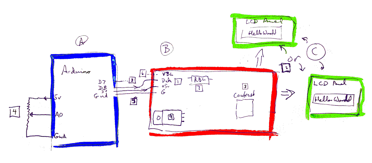
The Arduino is on the left, in blue, marked "A"
The controller is in the middle, in red, marked "B"
At the right, where I put "2" in the square box, there are two green boxes, standing for the LCD panel. No, you can't connect two panels to one controller. The reason I've drawn two is to underline the fact that the controller can be connected to LCD panels which use one row of 16 pins, OR to panels which use two rows of eight pins. If for some reason you wish to connect the panel to the controller with a bit of ribbon cable you can, but in many cases, you will plug the controller directly into the panel, and it happily sit behind the panel.
If you have a new controller and panel in front of you, you can and should test it before connecting it to your Arduino. Connect controller to panel, and 5v and ground to the controller, on the relevant pins in the board's upper left hand corner. (The 5v and ground connections are two of the 4 pins marked "1" on the diagram.)
A note about "ground" for novices: I will use this term quite frequently. If you connect to a "zero volts" part of the circuit, you have connected to (the) "ground". The "zero volts" wire from whatever you are powering things from needs to be connected to ground. The grounds of all the elements... power (voltage) source, Arduino, controller, LCD panel, need to be connected. If later you add a separate power source for the backlight, it's ground must be connected to the other grounds.
Once the controller-and-panel assembly has power, even without an Arduino connected, you should see a flashing cursor. The excellent notes provided by ModernDevice will give you more testing and set-up information should you want it. You really should read it carefully sometime, but if you are seeing your flashing cursor, you can postpone that. If your panel needs a backlight, if you look closely, with the panel under a bright light, you should see the flashing cursor, even if the backlight isn't (yet!) working.
(With only 5v and ground connected to the controller + LCD, if you press and release the 117 controller's "reset" button, you should see the backlight on (if you have one!) for about a second, and a brief message. If you have the "OP" button down as you press and release the reset button, and then release the OP button, you should see the various characters the display can give, and the backlight should stay on until you press reset again. That's some of the Good Stuff. DO read the ModernDevice notes, though! There's more.)
(The question of how to operate the backlight is covered at this thread at the Arduino forum. In a nutshell: The ModernDevice board is well designed to give you lots of choices about what you do with your backlight. The only bad news is that it can't drive some high power electro luminescent backlights.
Either now, or later, you may want or need to adjust the "contrast" setting. This is done with the potentiometer on the controller labeled "3" in the diagram, and "contrast" on the board in real life. Backlight issues may be involved, but basically, changing the contrast should take you from pale (or invisible) characters on a clear field, through a sensible state (dark characters/ clear field), and on to very dark characters against a quite dark field. (In some cases, the whole thing is done the other way around: clear characters against a dark background.)
Back to what we were doing here... getting acquainted with how nice and easy it is to connect your Arduino to an LCD display via a 117 controller.
At "4" in the diagram I have drawn a potentiometer connected to the first of the Arduino's analog inputs. This isn't "needed" to use an LCD panel with the Arduino! It is just there so that we will have something to display on our panel once it is properly hooked up.
At "5" we have the important connections between the Arduino and the controller. Just three wires! And "5v" and "Ground" barely count, do they. While in the example, I've used D8, you do not have to use that. More on this later. Use D8 for now.
That's it! The hardware is set up! Not too awful? The software is about as easy....
The following program will "look" at the voltage connected to the Arduino's first analog input once a second, and display the value obtained on the LCD panel. (That number will not be in volts, by the way.)
/*Arduino to LCD
ver 28 Dec 09

Expects an analog input to "A0"

Displays reading on a LCD panel,
via a ModernDevice.com/ Peter Anderson LCD controller
(Kit LCD117)

The controller is driven by one digital output from
Arduino, plus one more pin should be set aside for an
unused RX channel
*/

#include <SoftwareSerial.h>

int intAnValue=0;
const byte AnInputPin=0;//ADC pin that voltages will be fed to
const byte txLCDPin=8;//Pin messages for LCD will be sent on
const byte rxLCDPin=7;//Pin messages from LCD could be sent on... We
//aren't going to make any connections to this pin, or use any messages
//from the LCD.. but we have to provide a number to the software
//AS IF we might be making the connection/ reading the messages.

SoftwareSerial myLCDSerial =  SoftwareSerial(rxLCDPin, txLCDPin);

void setup()
{
  pinMode(txLCDPin, OUTPUT);
  pinMode(rxLCDPin, INPUT);
  myLCDSerial.begin(9600);//  setup connection to LCD
  myLCDSerial.print("?f");//Clear LCD screen
}

void loop()
{
  intAnValue=analogRead(AnInputPin);
  myLCDSerial.print(intAnValue);
  myLCDSerial.print("?n");

  delay(1000);//To slow down how rapidly readings are taken.
}
I said it was simple! If you want to stop reading here, you've had most of the Good Stuff. But I will add some comments about odds and ends which might clear up puzzles, etc.
Don't forget that I pointed you elsewhere for questions about the backlight. This is a light (hence the name!) that many LCD panels have behind (in back of) the "heart" of the LCD. That "heart" is a "sandwich" which, when electricity is applied, is transparent in places, opaque in others. Some LCD displays depend on light from outside the device shining thorough the clear areas, bouncing off a shiny backing, and re-emerging to make bits of the display light colored. The opaque parts of the "heart" look black when viewed this way. If the contrast setting (discussed previously) is not right, either the areas that should be dark are not as dark as they can be, or the "clear" areas are not as clear as they ought to be. Adjusting the "contrast" variable resistor ("pot") allows you to get the best possible balance between clear bits dark and dark bits clear. That's One Thing. Whether things are dark or light OVERALL is the job of the backlight is the other thing. The pin marked "6" in the group marked "1" at the controller's upper right is there to allow you to supply voltage to the backlight... but don't hook anything to that until you've read up about the "current limiting resistor" (marked "RBL", and with a "7" in the usual square box.)
In the diagram I showed D8 being used to drive the controller. As long as you change the....
const byte txLCDPin=8;//Pin messages for LCD will be sent on
... and just that line, by the way, that was the advantage we obtained by creating the constant "txLCDPin"...
... change the 8 to, say, 5, then you can use D5 for the line carrying data to the controller.
While you can, in theory, use any of the digital lines... or even the analogs, if you know the trick... for this task, you will avoid various other "issues" if you choose to use a line in the range D4-12, inclusive.
In the diagram, and, if you look closely, in the code, there is reference to the Arduino's D7, marked on the diagram with "8" in a square box. (Sorry about the numbers... "8" for D7... it's just where I'd got to.)
Like the earlier assignment of 8 to txLCDPin, to define D8 as the pin over which we will send data to the LCD module, the code has a line saying...
const byte rxLCDPin=7;
That prepares the way for...
SoftwareSerial myLCDSerial = SoftwareSerial(rxLCDPin, txLCDPin);
The effect of that line is to set things up for sending serial data out of the Arduino on D8, and reading it in via D7. Now, as it happens, the LCD module doesn't generate any data, so we are "wasting" D7, dedicating it to data which is never going to arrive.
It seems a pity, and inelegant, to waste a pin thus, but the "SoftwareSerial" needs to be given something for it's first parameter. The Arduino is so well endowed with I/O pins that you may have one to spare.
Again, we can use a different pin, and again sticking to D4-12 will save you having to think about other things. You shouldn't set rxLCDPin and txKLCDPin to the same number. Sorry, nice try.
I know I said that you had to look elsewhere for help with controlling the backlight brightness. But I will tell you a little bit here. On the diagram, marked with the "9" in a square, is a transistor. We'll come back to it in a moment.
The backlight is essentially an LED. If you feed voltage to pin VBL of the controller, marked "6", part of the group of four pins at the upper left ("1"), it goes to RBL ("7"), and from there to the backlight in the LCD panel. The circuit continues onward from the "LED", out of the panel, and back to the controller.
If, in the controller, that line then went straight to ground, we'd be done. Choose the right resistor for RBL, and the backlight would come on nicely. (Too high an RBL, and the backlight won't be on at all, or maybe it will be on, but as bright as it can be. Choose too low a value for RBL, and the backlight will be permanently damaged... or fried, to use the technical term. The panel's datasheet is where you have to look.) The "right resistor" will change if you change the voltage being fed in on VBL.
A moment ago, I said "If... that line.. went to ground...". Well, it doesn't... directly. It goes to ground through the transistor. The base of the transistor is connected to one of the outputs of the microprocessor at the heart of the controller. If the controller is given one command, the signal to the base makes the transistor act like a bit of wire, and the backlight comes fully on. A different command makes the signal to the base make the transistor "switch off", it no longer conducts, and the backlight goes off. With some backlights, you can have the brightness at intermediate levels, too.
Now, you'll have to learn about "the right commands" and how to send them elsewhere. That's the bad news. The good news is that if you just want to Make It Work, sacrificing the chance to alter the brightness by commands in your software (a bad idea), or if you just want to run some tests, before tackling the programming issues (maybe helpful!) you can just carefully short the top two pins of the transistor. When you've done that, you will have created a path to ground, to complete the circuit for turning on the backlight.
I hope that was useful. I tried not to do too much "teaching" in the above. If you want to have a more through explanation of all that is going on, and learn other things at the same time, head on over to my tutorial about using an LCD panel and the Arduino system's "serial monitor"! But i warn you... it is longer than most of my tutorials!
Here is how you can contact this page's editor. This page, and the software it references, ©TK Boyd, 1/2010.
Page tested for compliance with INDUSTRY (not MS-only) standards, using the free, publicly accessible validator at validator.w3.org