Many of the chips in the 1-Wire family from Dallas Semiconductor can be powered "parasitically"... that's Dallas's (apt) name for the system used.
The advantage of parasitic powering is that it means you can have a two wire MicroLan. ("MicroLan" is just Dallas's trademarked name for a bunch of 1-Wire chips "playing nicely" with each other and a "master" device, e.g. a PC or simple microcontroller, e.g. Arduino, in charge of the network of 1-Wire sensors, actuators, storage units, etc.) If you don't use parasitic powering, then you need to run three wires from chip to chip to chip. (An aside: You should be aware that MicroLans don't like star topographies. If you need a star, you need a hub to split it into separate, non- star, legs.)
I've often used parasitic powering entirely successfully. However, if you have a lot of chips on the MicroLan, or high poll rates, the time may come when supplying the chips which can be powered parasitically makes sense. It isn't difficult... especially if you provided for the possibility that you'd like to make the change when you first set up your MicroLan.
Just as an example, let's consider a MicroLan that is reading temperatures in various parts of a large greenhouse.
We'll assume you're using chips from the DS182x family, in a TO92 package, the little blob of plastic with three "legs".
To use those chips parasitically, you just connect two of the legs to one another, and that leaves you with two connections which go to the two wires of the basic MicroLan.
Now... and this is what I meant about giving yourself options for the future... rather than doing that the "obvious" way, using either a small PCB, or simple discrete wires, connect each of the three pins to a separate track or wire, and THEN make your connections to the MicroLan. If later, you want to use non parasitic power, then all you have to do is change a link, or disconnect one of the wires, and you can then supply the chip with its independent V,cc easily, without disturbing what would be fiddly connections to the package's pins.
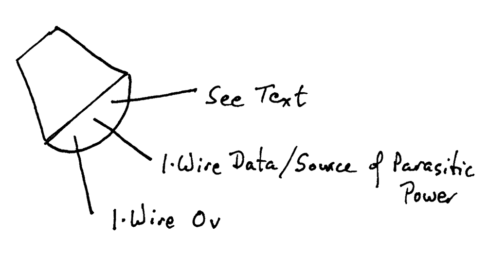
Here are the details of which pin is which on the DS1820. The DS18B20 and DS1822 use the pins the same way...

The DS1820's middle leg goes to the 1-Wire data line.
The DS1820's leg marked "See text" should be attached to the 5v, or, for parasitic power, connect this pin to ground (zero volts))
And the DS1820's "1-Wire 0v" should be attached ground,i.e. to zero volts.
(If the above seems over-explained, please remember that this page may be accessed by people who want more than just an idea of what this "parasitic power" thing is all about.)
So... that's the "how to" of it. Now let's look a little deeper at what is going on.
Anything electronic needs a source of power. It must be "fed" with a voltage. All of the 1-Wire chips can "talk" with the master controlling the MicroLan, so there must be a "data" line between them.
When a 1-Wire chip is powered parasitically, here's what happens: For much of the time, the master controller keeps the voltage in the one wire between it and the 1-Wire chip at 5 volts. (That wire is called the data/power line.) During this time, a tiny capacitor inside the chip is charged up until it is "full". Think of it as a mini rechargeable battery. Once in a while, the master (or, if given permission, a moment earlier, one of the controlled chips on the MicroLan) will make the data/power line go to zero volts. Every chip on the MicroLan will "see" that change of voltage. The pattern of highs (5v) and lows (0v) is used as a "Morse code" with which the master sends commands out to the 1-Wire chips, and with which they "answer" back.
What's cool is that as long as the "talking" phase, when the data/power line is sometimes low, is isn't going on all the time, the capacitors in the chips act like little "UPS"es inside each 1-Wire chip, tiding it over the times when the power (and data) line is at zero volts. The idea is simple. I bet getting the design right was less than simple!
![]() Page WILL BE tested for compliance with INDUSTRY (not MS-only) standards, using the free, publicly accessible validator at validator.w3.org
Page WILL BE tested for compliance with INDUSTRY (not MS-only) standards, using the free, publicly accessible validator at validator.w3.org
....... P a g e . . . E n d s .....