This page is seriously dated, 1/17.
In 12/16, I wrote a NEW explanation of using 1-Wire temperature sensing chips like the DS18B20 with an Arduino (or ESP8266, Teensy, etc!). Read that FIRST if you are new to the topic
However, for now, I am leaving the rest of this page here, in case you have read everything else, and are still seeking that "Eureka" moment which WILL come, if you just bang your head against the wall long enough, and come at it again and again from differnt angles!
This tutorial shows you how to access a DS18B20 temperature sensor to an Arduino. It was written in connection with the nuelectronics datalogging shield, but you don't need a shield to use the information here.
This may not be the best tutorial on the web about using the Dallas temperature sensors with Arduinos... but it does come with the sourcecode to make at least one of them accessible! And I have tried to keep the code simple, to help people who are making a start.
Don't be scared by the "DS"... yes, this is a chip from the Dallas Semiconductor 1-wire family , but you don't have to deal with the usual 1-Wire programming things. You DON'T need the general Arduino 1-Wire library... or, for that matter, any extra libraries. (For using your shield to read temperature sensors.)
Note that all the shield is doing here is providing a convenient mechanical "interface" between the sensor and the Arduino. What follows could be used even if you didn't have the shield.
A detail: You will see "one wire" and "one wire interface" in the nuelectronics documentation. This is not always connected with "1-Wire" (a Dallas trademark) at all, and even when you are connecting a 1-Wire device to a nuelectronics "one wire" connection point, you won't often (ever?) get dragged into some of the more complex 1-Wire issues. Don't get me wrong... I like 1-Wire... it is powerful. But to get everything you can from 1-Wire gets dangerously close to Serious Work. neElectonics lets you use some of the (marvelous) 1-Wire devices without the work! (I've written a brief note about the potential for confusing "one wire" and "1-Wire", if you are still nervous.)
Another detail: This will work exactly as written to read temperatures with one or more DS18B20s. If you have DS1820s (no "B" in name), they connect to the shield exactly as DS18B20s do, but you have to modify the code slightly.
The DS18B20 is a member of Dallas's "1-Wire" family. That family is capable of clever things... like having multiple sensors on a single pair of wires.
Doing clever things takes clever software. We, here, are going to use the chip "crudely". But we won't be giving up the advantages it has which lead to accurate temperature readings. One "price" of our shortcut: we'll only be able to connect one temperature sensor to each of the sockets of the nuelectronics datalogging shield for the Arduino.
This shortcut doesn't change the fact that the DS18B20 (and DS1820) return the temperature it is sensing in a digital form. The DS18B20 datasheet says...
(I haven't looked into what resolution we are working at.)
Don't be downhearted by the "+/- 0.5°C accuracy". I think the sensors are better than that might make you believe. Either skip the rest of this paragraph, or press on prepared to not worry too much.... I believe that Dallas are saying that if the sensor says, say, 15.0°, then it is in the range 14.5° to 15.5°... but I also believe that any "error" will be consistent to a much tighter standard. If the sensor reports that the temperature is now 15.2°, I believe you can trust the message that the temperature has risen by 0.2°.... you just can't be sure exactly what the temperature is in absolute terms.
The following is the pinout for both the DS1820 and the DS18B20...
The nuelectronics datalogging shield has a number of sockets around its edge. In every case, one of the outside pins carries 5v and the other outside pin carries 0v, or "ground". The middle pin or pins connect to one of the Arduino's analog pins. (Which can also be used for digital i/o... a story for another day.)
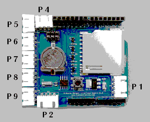
Plug your DS18B20 sensor into P4 for the purposes of this tutorial. P4 brings ADC0 to the edge of the shield. (Of course, you can plug your DS18B20 in elsewhere, but that requires a tiny modification of the code. When you are ready to consider using a different connector, you can find the information you need on my "Naming of parts" page.)
If you bought a DS18B20 module from nuelectronics, you just plug it in. If you have a connector for the sort of socket used, with a further 3 way socket on the far end of the connector, and a loose DS18B20, you can just "plug it in" to the socket on the end of the connector.... but you must get it the right way up. (That's the bad news. The good news is that the order of the pins and the order of the signals on the connector make "plugging in" easy.)
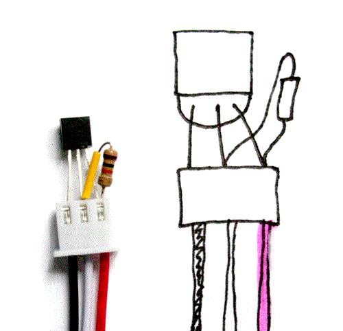
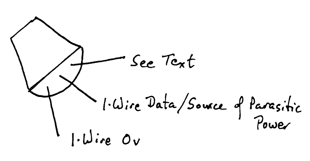
IN THE ILLUSTRATION... to the right: From left to right, the wires are black, white, red. Ground, data, 5v. Note which side of the DS1820 is up.
BE CAREFUL: do not plug the chip in backwards, "upside down". (Refer to diagram) The "1-Wire 0v" pin (left hand.. as drawn..) goes to the Arduino ground. The middle pin goes to the Arduino data pin. The (right hand)"See Text" pin goes to the 5v supplied by the Arduino. (We are not using the chip in "parasitic mode".
Bad news! You must ALSO connect a 4k7 ohm resistor (4700 ohms) between the middle pin of the sensor and the 5v line. Don't you wish you'd just bought the one made for you by nuelectronics? That has the resistor already in place!
Good news: In a fit of "poke and hope", when I couldn't find a 4k7 resistor, I tried a 10k resistor. It "worked". Reliably? I don't know. I will order some 4k7s, if need be!
More good news... I was even able to "attach" the resistor by shoving it's leads down the connector, alongside the DS18B20's leads. Not perfect. Not the "finished product"... but enough to satisfy me that the thing works!!
Information: If your sensor returns "85" (degrees C), it is "saying" "Something is wrong." (85 is a rogue value
That's it! Your sensor is connected!
As I think I said elsewhere, you do not need the Arduino OneWire libraries to read the sensor, or any other extra libraries for what is presented in this tutorial.
The following code reads the sensor once every 10 seconds, and reports the temperature sensed to the serial monitor. Obviously, in a "serious" application, you would be unlikely to tie up your big computer to make a "screen" for the Arduino's output... this program is just to show you how to read from the sensor. Once you've mastered that, what you do with the temperature you are given is up to you!
Note 1: If you change the "14" in the line "#define TEMP_PIN 14", you can change where the program looks for the temperature sensor. In other words, the temperature sensor(s) can be connected to the shield wherever you want, as long as you modify the program to allow for where you are connecting them.
Adding a second, third, etc, sensor doesn't take much more than adding a "#define TEMP_PIN2 15", "#define TEMP_PIN3 16", etc, and adding an extra "read it" line and an extra "report answer" line.
Note 2: The three lines at and following "See note 2" are just "setting the stage" for the declaration of some subroutines later in the code. In another language, I would call these "forward declarations". Maybe that's the right term in C, too. ("Arduino-Speak" is a dialect of C).
/*ReadDS18B20
ver: 6 Jly 2010
THIS IS A FIRST DRAFT.... WORKS, but scheduled for overhaul.


Simple, simple test of reading DS18B20
connected to nuelectronics.com datalogging shield.

See...

http://sheepdogguides.com/arduino/ar3ne1tt.htm

... for explanation of this code.

Code lightly adapted from code from nuelectronics.com*/

#define TEMP_PIN  14 //See Note 1, sheepdogguides..ar3ne1tt.htm

void OneWireReset(int Pin);//See Note 2
void OneWireOutByte(int Pin, byte d);
byte OneWireInByte(int Pin);

void setup() {
    digitalWrite(TEMP_PIN, LOW);
    pinMode(TEMP_PIN, INPUT);      // sets the digital pin as input (logic 1)
Serial.begin(9600);
//9600 to match the data rate being used by the
//serial monitor on my system, which is set to
//the Arduino default. (Sample code published
//by nuelectronics used a faster baud rate.)
    delay(100);
    Serial.print("temperature measurement:\n");
}

void loop(){
  int HighByte, LowByte, TReading, SignBit, Tc_100, Whole, Fract;

  OneWireReset(TEMP_PIN);
  OneWireOutByte(TEMP_PIN, 0xcc);
  OneWireOutByte(TEMP_PIN, 0x44); // perform temperature conversion, strong pullup for one sec

  OneWireReset(TEMP_PIN);
  OneWireOutByte(TEMP_PIN, 0xcc);
  OneWireOutByte(TEMP_PIN, 0xbe);

  LowByte = OneWireInByte(TEMP_PIN);
  HighByte = OneWireInByte(TEMP_PIN);
  TReading = (HighByte << 8) + LowByte;
  SignBit = TReading & 0x8000;  // test most sig bit
  if (SignBit) // negative
  {
    TReading = (TReading ^ 0xffff) + 1; // 2's comp
  }
  Tc_100 = (6 * TReading) + TReading / 4;    // multiply by (100 * 0.0625) or 6.25

  Whole = Tc_100 / 100;  // separate off the whole and fractional portions
  Fract = Tc_100 % 100;


  if (SignBit) // If its negative
  {
     Serial.print("-");
  }
  Serial.print(Whole);
  Serial.print(".");
  if (Fract < 10)
  {
     Serial.print("0");
  }

  Serial.print(Fract);

      Serial.print("\n");
  delay(5000);      // 5 second delay.  Adjust as necessary
}

void OneWireReset(int Pin) // reset.  Should improve to act as a presence pulse
{
     digitalWrite(Pin, LOW);
     pinMode(Pin, OUTPUT); // bring low for 500 us
     delayMicroseconds(500);
     pinMode(Pin, INPUT);
     delayMicroseconds(500);
}

void OneWireOutByte(int Pin, byte d) // output byte d (least sig bit first).
{
   byte n;

   for(n=8; n!=0; n--)
   {
      if ((d & 0x01) == 1)  // test least sig bit
      {
         digitalWrite(Pin, LOW);
         pinMode(Pin, OUTPUT);
         delayMicroseconds(5);
         pinMode(Pin, INPUT);
         delayMicroseconds(60);
      }
      else
      {
         digitalWrite(Pin, LOW);
         pinMode(Pin, OUTPUT);
         delayMicroseconds(60);
         pinMode(Pin, INPUT);
      }

      d=d>>1; // now the next bit is in the least sig bit position.
   }

}

byte OneWireInByte(int Pin) // read byte, least sig byte first
{
    byte d, n, b;

    d=0;//This critical line added 04 Oct 16
    //I hate to think how many derivatives of
    //this code exist elsewhere on my web pages
    //which have NOT HAD this. You may "get away"
    //with not setting d to zero here... but it
    //is A Very Bad Idea to trust to "hidden"
    //initializations!
    //The matter was brought to my attention by
    //a kind reader who was THINKING OF YOU!!!
    //If YOU spot an error, please write in, bring
    //it to my attention, to save the next person
    //grief.

    for (n=0; n<8; n++)
    {
        digitalWrite(Pin, LOW);
        pinMode(Pin, OUTPUT);
        delayMicroseconds(5);
        pinMode(Pin, INPUT);
        delayMicroseconds(5);
        b = digitalRead(Pin);
        delayMicroseconds(50);
        d = (d >> 1) | (b<<7); // shift d to right and insert b in most sig bit position
    }
    return(d);
}
So! There you have it. Delightfully simple. I was using 1-Wire temperature sensors LONG before I started using the Arduino, and I can assure you that it is not always this easy!
The ideas above are taken just a little further in my next "How To" essay, in which I explain how to connect two (or more) DS18B20s to a microprocessor, e.g. Arduino.
I have a "FarWatch" weather station online which reads many things with 1-Wire chips. I also have a page explaining how that weather station was set up.
Further to the Arduino ideas the page you are reading now will take you to, I have posted a series of essays which try to help you become a better Arduino programmer and engineer... but, for the best result, you will have to buckle down and work your way through them in sequence. The "How To's" here can be accessed in whatever order you like.
Feel free to use this information in programming courses, etc, but a credit of the source would be appreciated. If you simply copy the pages to other web pages you will do your readers a disservice: Your copies won't stay current. Far better to link to these pages, and then your readers see up-to-date versions. For those who care- thank you- I have posted a page with more information on what copyright waivers I extend, and suggestions for those who wish to put this material on CDs, etc.
See the discussion near the bottom of the "top level" page covering the bulk of my Arduino contributions. There is information there, too, about things like "May I copy your material?", and the system of file names I am trying to work to.
If you visit 1&1's site from here, it helps me. They host my website, and I wouldn't put this link up for them if I wasn't happy with their service... although I was less than pleased the other day to have what I was doing interrupted by a telephone call from their sales team, trying to get me to extend my involvement. Sigh. Hardly a rare event, but I'd thought 1&1 were a bit classier that some of the people who have my telephone number.
Click here to visit editor's Sheepdog Software (tm) freeware, shareware pages.
Click here to visit the homepage of my biggest site.
Click here to visit the homepage of Sheepdogsoftware.co.uk. Apologies if the "?Frmar3ne1tt" I added to that link causes your browser problems. Please let me know, if so?
![]() Page has been tested for compliance with INDUSTRY (not MS-only) standards, using the free, publicly accessible validator at validator.w3.org. Mostly passes.
Page has been tested for compliance with INDUSTRY (not MS-only) standards, using the free, publicly accessible validator at validator.w3.org. Mostly passes.
AND passes...

....... P a g e . . . E n d s .....