This page will tell you what signals the nuelectronics datalogging shield for Arduinos brings to the edge of the shield. It will tell you the names nuelectroincs has given those connectors.
(The title I assigned this page comes from Henry Reed's World War II poem, Naming of Parts)
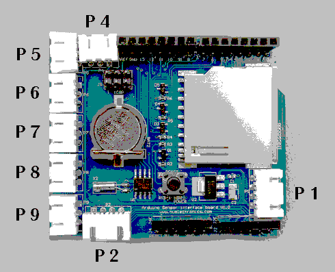
If you look at the edge of the board carrying P5 to P9, you will see that each connector has three pins...
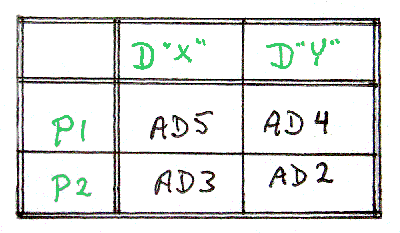
P4 ("top" edge) is also a 3-way connector, while P1 and P2 are 4-way connectors.
Note that there is no P3 connector in the image I've based this information on. The group of 6 pins in the center of the shield, labelled "ICSP" are marked "J5"... perhaps they were once the "missing" P3. Don't worry. That's what my friends are always telling me, anyway.
The connectors are drawn "the same way up" as they are shown in the photo. In both cases, notice, the outside pins carry 5v from the Arduino, for the use of your peripheral, and the Arduino's ground, or "zero volts" line. Note that you must take care not to draw too much power from whatever is supplying the Arduino. Furthermore, different, almost certainly lower power-draw limits apply to what you should draw out of the middle pin of pins in the connectors. You can't, for instance, directly control a motor through one of those pins.... but I digress into general Arduino points that are addressed elsewhere.
Getting back to the shield....
The following tells you what Arduino signal is on the center pin for the connectors P4- P9. The second line is the analog signal number, the last line the alternative digital signal number. In other words, if you connected something to connector P4, you could read the voltage there with analogRead(0). Nothing special is happening to that line inside the shield, so you could also send a 50% duty cycle (128) PWM signal out over P4 with analogWrite(0,128). And, again "nothing special"... just how the Arduino's analog pins normally work... you can also use digitalWrite(14,LOW) out on P4, if you have done pinMode(14,OUTPUT) first.
 P4  P5  P6  P7  P8  P9  <--Connector ID
  0   1   2   3   4   5  <-- Analog line ID
 14  15  16  17  18  19  <-- Digital line ID
... and the assignment of signals to pins on P1 and P2 will be clear from the following, I hope? (see the 4-way connector diagram, above, for the meaning of "X" and "Y".)
(I believe the type designator for the connectors is "JST XH", by the way. They are 2.5mm pitch connectors, which I believe is implicit in the "XH".)...
Be sure to note that the analog lines 2,3,4 and 5 (aka digital lines 16-19) are brought to BOTH P6-P9 and to P1/P2. It would be a rare situation where you could, for instance, use P6 and P2 at the same time. There's more on what Arduino data lines are used, and which are free for your use at my page on Arduino interface lines used.
Quite reasonably, nuelectronics calls P4-P9 "one wire" connectors, and P1 and P2 "two wire" connectors. Unfortunately, a semiconductor company (Dallas) has a trademark, "1-Wire", and even worse, you might want to connect 1-Wire devices via a one wire connector! This isn't really too terrible, just so long as you remember to keep the terms clear in your head. I've written a brief note that says all of that again, if it is still unclear to you at this point.
So... I hope that gives you a good grounding in the names of the different parts of the nuelectronics datalogger shield, and the information that you need about where to find the different signals you will need to use for your projects?
-------------------
Further to the Arduino ideas the page you are reading now will take you to, I have posted a series of essays which try to help you become a better Arduino programmer and engineer... but, for the best result, you will have to buckle down and work your way through them in sequence. The "How To's" here can be accessed in whatever order you like.
Feel free to use this information in programming courses, etc, but a credit of the source would be appreciated. If you simply copy the pages to other web pages you will do your readers a disservice: Your copies won't stay current. Far better to link to these pages, and then your readers see up-to-date versions. For those who care- thank you- I have posted a page with more information on what copyright waivers I extend, and suggestions for those who wish to put this material on CDs, etc.
See the discussion near the bottom of the "top level" page covering the bulk of my Arduino contributions. There is information there, too, about things like "May I copy your material?", and the system of file names I am trying to work to.
If you visit 1&1's site from here, it helps me. They host my website, and I wouldn't put this link up for them if I wasn't happy with their service... although I was less than pleased the other day to have what I was doing interrupted by a telephone call from their sales team, trying to get me to extend my involvement. Sigh. Hardly a rare event, but I'd thought 1&1 were a bit classier that some of the people who have my telephone number.
Click here to visit editor's Sheepdog Software (tm) freeware, shareware pages.
Click here to visit the homepage of my biggest site.
Click here to visit the homepage of Sheepdogsoftware.co.uk. Apologies if the "?Frmar3ne1nop" I added to that link causes your browser problems. Please let me know, if so?
![]() Page tested for compliance with INDUSTRY (not MS-only) standards, using the free, publicly accessible validator at validator.w3.org
Page tested for compliance with INDUSTRY (not MS-only) standards, using the free, publicly accessible validator at validator.w3.org
....... P a g e . . . E n d s .....