 Recommend to StumbleUpon
Sparkfun produces a module that lets you connect graphics capable LCD displays to any source of TTL serial data... e.g. an Arduino, or a Pi.
The serial backpack for LCD graphics panels was selling for $20 (plus p&p) Feb 2018. To that you would need to add a panel, and connect them (a simple matter of a line of 20 pads). (Sparkfun at one stage sold "assembled" units... but it isn't hard to "assemble" your own!) At 2/18, the offered a suitable 128 x 64 pixel panel for $20, and a 160 x 128 panel at $50. I infer from the description of the first that the serial backpack should be okay with any LCD panel using the KS0108B parallel interface chipset. I'm not sure how well you would get on with panels of different dimensions.
(Circles, diagonal lines, or "raggity" lines, say a graph of temperature readings, are also easy.)
Is it "perfect"? No. Can it be useful? Certainly!
Enough about the "what"!!! Now for the "how"!
Arduino code illustrating use of the Sparkfun LCD-09352 backpack is available (for free). It is the code I used to check the claims made above.
I connected my Sparkfun graphics/ text LCD display to a 5v Arduino with three wires, wrote the following "program", and it Just Worked!) Note: I didn't need the library Sparkfun provides. (If you haven't used SoftwareSerial before, a library I DO use, don't be alarmed... that's just one of the standard Arduino libraries. (I have nothing against the Sparkfun library. I just prefer to do without third party libraries, when I can.)
But! It "shouldn't" have. Not reliably. Sparkfun recommend an external power supply. (I'll explain my "3 wire" solution in a minute.) And they warn that if you must cut corners, and power the display from a USB source, be sure that it is delivering a "good" 5v... not the 4.5v that you sometimes see from cheap power supplies.
Having said that, though... my display worked fine in short tests powered only from the Vcc pin of my Arduino Pro Mini, powered by the programming cable tying it to the PC the Arduino code was created on.
So! The three wires: I connected the backpack's GND to the Arduino's GND, the backpack's Vin to the Arduino's Vcc, and the "Rx" pin of the backpack... that's "Receive data TO the backpack" to the pin for my Arduino's D10. For reasons which I hope will become clear, I also, while running the software I used, left the pin for D9 unused. (Yes, in an Arduino running the program below, D10 is the transmit, the data OUT line... from the Arduino's point of view. You connect the Arduino output's to the dislay's input. Logical, when stated like that, but sometimes the "Tx" (transmit, output) and "Rx" (receive, input) designations confuse people. The confusion arises when you aren't clear about Tx or Rx from whose point of view?)
With those connections the following should put "Hi Arduino" on the LCD... but don't worry if it "doesn't work" at first... keep reading!
/* NGL-TestPcb270-minimal
Version: 26 Feb 18
Started: 26 Feb 18
*/

#include <SoftwareSerial.h>

SoftwareSerial MySerial(9,10);// RX, TX

void setup() {

  MySerial.begin(115200);
  delay(800);//A delay after a ((serial)).begin gives the
     //system a chance to "settle" after the channel is
     //established.
  MySerial.print("Hi Arduino");

}// end of setup()

void loop() {
//loop() empty
}// end of loop())
Now... if you've run that, and it "isn't working"... don't despair!
a) Has the backlight behind the LCD come on? (You can tell by looking at the display edge-on.) If not, it isn't getting the power it should.
You've got power? Good! No text, after running the program? (Be sure it DID compile, and upload!)
On the back of the backpack there is a small potentiometer. (Circular, about 2mm across. "Silver". Fragile! 1/4 of the way across the top edge.) Try turning this. At the very least, the LCD should vary from transparent to opaque. I hope that between the two, you will find the Goldilocks state where some pixels are blocking the backlight and others are not... revealing your "Hi Arduino"! (If something else thwarted your first attempts, and you resolved the "something else", please get in touch, so I can write up for the next person?)
A nuisance: If you've played with the display a bit before seeing this essay, then there's a remote chance that you changed it's baud setting. It remembers a baud rate setting changes, even after a power off/ power on cycle. (It also remembers some other things, but none are the "deal wreckers" that a changed baud rate are.
In the Sparkfun guide to the backpack, it says "... the baud rate can be reset to 115,200. During the one second delay at power up, send the display any character at 115,200bps." Whew!
I said it wasn't perfect.
It does seem sometimes to "fall behind" the processor, if you try to drive it too quickly. There is no handshake between the two of them.
As will all product development, start small. Build towards your goals in small steps.
Make sure you can display "Hello World" before you try to be "clever". If you get nothing... check contrast pot. If you get nothing but gibberish... check baud rate. Once you're coming close to "Hello World", think about your wiring an power supply. Even if they are "great", then it may be worth reducing the baud rate from the default. This (reducing baud rate) is not without its perils, but may be worth the exercise. And last, certainly not least: Insert small delays here and there. I found that 80ms after a screen clear, or after sending a line of text to the display was often helpful. (I was using 9600 baud to send the commands at the time I settled on the 80ms delay.)
The device does not hold your hand. If you write over-long lines of text to it, things get scrambled pretty quickly. So compose your lines carefully! Don't expect advanced wordwrap facilities in a great little module. Great if you recognise and work with it's limitations!
The Sparkfun guide to the backpack tells you about a number of simple (when you get the hang of it!) commands the backpack will obey.
Note: You don't need to have the Sparkfun library installed on your system to use those commands. (If you are happy to use the library, I have an alternate tutorial on the module that concentrates on that approach... it also has better graphics!)
Forgive me if I was being a bit dim, but I found the way the commands were presented a bit hard to follow. (Of course, by the time you read this, the Sparkfun guide may have been revised.)
People unfamiliar with the old dodge of using "an escape character" will have extra hurdles to overcome... but they are worth the trouble... using an escape character is a useful technique.
Take for example, the command to clear the LCD screen...
The Sparkfun explanation is as follows...
"((Send)) "<control>@ (0x00)" ((to clear)) the screen of all written pixels."
(They do go on to explain that in more detail!)
In theory, the following is all you need...
  MySerial.write(124);
  MySerial.write(0x00);//Clear screen
.. alas, for this particular command, an extra wrinkle raises its ugly head...
0x00 boils down to zero. And the compiler doesn't like zero, in this form, here. No problem, we just use...
  MySerial.write(124);
  MySerial.write(byte(0));//Clear screen
If you forget the "byte()" bit around the zero, you'll get an error saying "call of overloaded 'write(int)' is ambiguous".
Here's the "clear screen", twice, in a context, in hopes it can... forgive me... "clear" up any doubts you have...
void loop() {
  //Next two, between them, clear screen....
  MySerial.print("First hi....");
  delay(80);//A brief delay after any .print seems helpful.
  delay(1000);//and, because the screen is cleared next,
    //we need, a bit of time to read the message
    //is necessary. (Of course, one delay of 1080... or even
    //1000 "would do", but I wanted to emphasise that you
    //always want at least a little delay after a .print

  MySerial.write(124);
  MySerial.write(byte(0x00));//Clear screen

  MySerial.print("Second hi... WOW!");
  delay(80);
  delay(1000);//as before.

  MySerial.write(124);
  MySerial.write(byte(0x00));//Clear screen

}// end of loop())
"0x" is, by the way, a prefix, to say that what follows is written in hex. 0x00 is 0, written in decimal, the way we usually write these things. 0x10 is 16 in decimal. Numbers written this way always begin "0x" (that's almost "an" "escape character", as it happens!). Following the 0x there can be any digit, but also the letters A... F. (The case of the letters is not significant. 0x0f and 0x0F both mean fifteen (decimal)).
Nota bene: when Sparkfun said that to clear the screen, you send... "<control>@ (0x00)", they were saying what "the code" was two ways. <control>@ is another way of saying 0x00. And they were not repeating something they thought you'd always remember: ALL of the command codes have to immediately follow a "MySerial.write(124);" And the command code (0x00 in this case) is also sent with a MySerial.write...
(In your code, the "MySerial" part might be something else. It is only "MySerial" because earlier in the program I put SoftwareSerial MySerial(... with two numbers after it. The first number says what data line the serial data will be sent out on. The second number specifies a dataline for incoming data. (I think you have to have the second number, even though in this case we don't have any incoming data. Sigh.)
Onward!!
Other commands:
I hope you won't need it, but let's get the Change Baud Rate command out of the way. As I said, the device will "remember", even across a power off/ power on event, the most recent Change Baud Rate command it has seen.
To set the baud rate to 9600, you'd do...
MySerial.write(124);
delay(20);
  MySerial.write(7);//CHANGE BAUD RATE SETTING
delay(20);
  MySerial.write(0x32);//N.B 0x32 to set to 9600.... not 0x02
Of course, there's a bit of a Catch-22 going on here... unless you are successfully communicating with the device, you can't send it the command to communicate at a different speed!
The "delay(20)" lines may or may not be necessary. At worst, they do no harm. I wouldn't put a delay(20) after EVERY command I sent to the backpack. But if something isn't working, a small delay is worth a try.
If you send a byte to the backpack at 115,200bps while it is starting up, it will reset itself to communicate at 115,200bps.
If your device seems to "die", sometime after you've changed to a non- standard baud rate, just check that it hasn't reverted to 115200 somehow. If this happens to you often, I'd be interested to hear about it... especially if you can figure out why it does it!
See the Sparkfun guide for the backpack for the codes for the other baud rates.
Reverse display mode: Use...
  MySerial.write(124);
  MySerial.write(0x12);//reverse display mode.
Normally, the displays gives you black writing on green background, or white writing on a blue background. After a "reverse mode", they would be green on black, or... (blue on white(?) not sure!). Note that the display will "remember" the "reverse mode" command even after a power off/ power on cycle.
Draw Line: To draw a line, you issue a "Draw line" command, and, still using MySerial.write, send 5 more numbers. The first 4 are the coordinates of the line's start and end. The screen's 0,0 is at the UPPER left, by the way. You can write the numbers for the coordinated the way we would normally write them, if you wish, as long as you remember to put zero in "byte(0)" if it arises. (You COULD write 0x0C as 12, if you wished, as hex 0c is decimal 12... but I will continue using the hex equivalents, as that's how the command codes are shown in the Sparkfun note.)
The fifth number that you send after a "draw line" command should be 1 or zero, for "draw" or "erase" line, respectively. It is supposed to do that... or the reverse (0 to draw, 1 to erase)... but in my tests it didn't seem to do anything. And it may have been "littering" the landscape with a scrap that could be the source of problems. Sorry... I don't have a definite answer for you on this... yet. The same discussion could be repeated for every command with a "draw/ erase" parameter.
  MySerial.write(124);
  MySerial.write(0x0C);//draw line.
  MySerial.write(byte(0x00));//x coordinate of start... remember "byte" if saying zero
  MySerial.write(10);//y coordinate of start
  MySerial.write(40);//x coordinate of finish
  MySerial.write(20);//y coordinate of finish
  MySerial.write(1);//to make backpack DRAW line. (Zero here is
    //SUPPOSED to make backpack erase line. Doesn't seem to work.
Draw Circle: To draw a circle, you issue a "Draw circle" command, and, still using MySerial.write, send 4 more numbers. The first 2 are the coordinates of the circle's center. The third number is the circle's radius.
The 4th number that you send after a "draw circle" command should be 1 or zero, for "draw" or "erase" line, respectively... or vice versa. If it is working. See discussion in "Draw Line" command's discussion.
Circles can be drawn off-grid, but only those pixels that fall within the display boundaries will be written.
  MySerial.write(124);
  MySerial.write(0x03);//draw circle.
  MySerial.write(byte(20));//x coordinate of center
  MySerial.write(20);//y coordinate of center
  MySerial.write(12);//radius
  MySerial.write(1);//to make backpack DRAW line. (Zero here is
    //SUPPOSED to make backpack erase line. Doesn't seem to work.
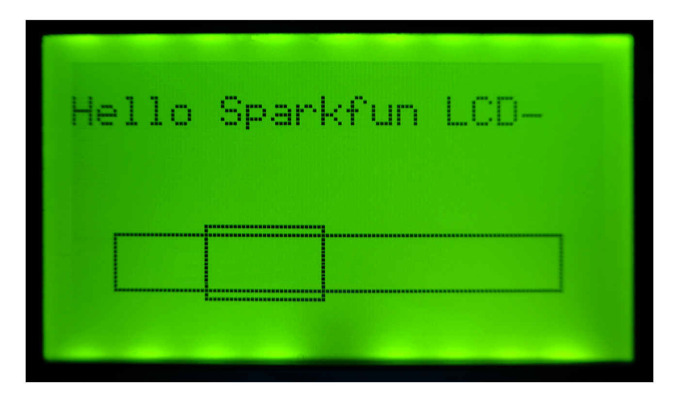
Draw Box: To draw an unfilled rectangle, you issue a "Draw box" command, and, still using MySerial.write, send 5 more numbers. The first 4 are the coordinates of the box's upper left and lower right corners.
The 5th number that you send after a "draw circle" command should be 1 or zero, for "draw" or "erase" line, respectively... or vice versa. If it is working. See discussion in "Draw Line" command's discussion.
  MySerial.write(124);
  MySerial.write(0x0F);//draw box.
  MySerial.write(byte(0x00));//x coordinate of upper left
  MySerial.write(10);//y coordinate of upper left
  MySerial.write(40);//x coordinate of lower right
  MySerial.write(20);//y coordinate of lower right
  MySerial.write(1);//to make backpack DRAW box. (Zero here to erase. Or vice versa. May not work!)
Erase Box: You can also erase a rectangle, and everything inside it. (The "Draw box" only drew (or erased, if you can get that working!) the lines around the edge of the box.)
The command is similar to the one you used to "Draw box" command, but using 0x05 in place of 0x0F. (The Sparkfun documents make no mention of a "draw or erase" fifth number for the "Erase" command, but there might be one. One value would turn all pixels in the box off, the other turn all on.)
  MySerial.write(124);
  MySerial.write(0x05);//Erase box.
  MySerial.write(byte(0x00));//x coordinate of upper left
  MySerial.write(10);//y coordinate of upper left
  MySerial.write(40);//x coordinate of lower right
  MySerial.write(20);//y coordinate of lower right
  MySerial.write(1);//to make backpack DRAW box. (Zero here to erase. Or vice versa. May not work!)
Set or clear one pixel: You can turn individual pixels on or off... great for drawing graphs. The following text is nearly just a copy of the Sparkfun text...
The 0x10 command, followed by x and y coordinates and a 0 or 1 to determine setting or resetting of that pixel sets or clears a pixel.
Here's a little demo showing setting of 2 pixels near the lower left of the display...
 MySerial.write(124);
  MySerial.write(0x10);//Set or clear pixel.
  MySerial.write(byte(0x00));//x coordinate
  MySerial.write(55);//y coordinate
  MySerial.write(1);//to set pixel
 MySerial.write(124);
  MySerial.write(0x10);//Set or clear pixel.
  MySerial.write(1);//x coordinate
  MySerial.write(56);//y coordinate
  MySerial.write(1);//to set pixel
... and then clearing the same pixels back to the "background" color...
 MySerial.write(124);
  MySerial.write(0x10);//Set or clear pixel.
  MySerial.write(byte(0x00));//x coordinate
  MySerial.write(55);//y coordinate
  MySerial.write(0);//to clear pixel
 MySerial.write(124);
  MySerial.write(0x10);//Set or clear pixel.
  MySerial.write(1);//x coordinate
  MySerial.write(56);//y coordinate
  MySerial.write(0);//to clear pixel
Again, nearly copying Sparkfun note about the "set/clear pixel" command: "Any pixel on the display can independently set or reset with this command. Remember that setting a pixel doesn't necessarily mean writing a one to that location, it means to write the opposite of the background. So if you're operating in reverse mode, setting a pixel actually clears the pixel and sets it apart from the white background. Resetting that pixel causes it to be white like the background."
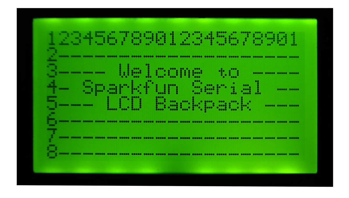
Set cursor: Suppose you want to "jump" to a particular place on the screen before writing some text. Nothing easier. Note that this "cursor setting" is in respect of where text will appear. If you set the cursor to X=0 and Y=0, the upper left corner of the next character sent to the display will be in the upper left corner of the screen.
If you do a number of println's, you will get a number of lines of text on the screen... you don't have to use multiple Set Cursor commands.... but you DO have to keep your lines to short enough to fit line nicely. (Too long lines cause jumbled results!)
Each character is 5 pixels wide, 7 pixels high... but "place" them on the screen as if they were 6 x 8, or else your characters will all be jammed up against one another!
MySerial.write(124);
  MySerial.write(0x18);//Set cursor X value
  MySerial.write(byte(0));
  delay(80);

MySerial.write(124);
  MySerial.write(0x19);//Set cursor Y value
  MySerial.write(35);
  delay(80);
Again... mostly from Sparkfun...
"Send 0x18 or 0x19 followed by a number representing a new reference coordinate changes the X or Y coordinates. The X and Y coordinates are used by the text generator to place text at specific locations on the screen. The coordinates refer to the upper left most pixel in the character space. If the offsets are within 6 pixels of the right edge of the screen or 8 pixels of the bottom, the text generator will revert to the next logical line for text so as to print a whole character and not parts. Attempting to set values greater than the length of each axis result in maximizing the respective offsets."
I got in a bit of a tangle, after using the set X/ set Y commands. The backpack seemed to "remember", even across a power off/ power on cycle, previously issued set X, set Y commands, and the next MySerial.print("Hi") placed the text as if I had issued the set X/ set Y again... I think. But that makes no sense. (At worse, you'll need to issue "set X to zero", "set Y to zero" commands to overcome this problem... if it even exists! I would expect a power cycle to clear such things. But remember: It DOESN'T clear a "reverse mode" command, or a change baud rate command, so maybe it "remembers" set Xs, too!
I think these weird things stopped happening when I began...
If things are being odd... add a delay(80); I think that the backpack is sometimes "doing things" when the processor sends a message, and that in these cases, the backpack just ignores what it was sent. So don't send new stuff too quickly.
-----------------
One last command: To control the brightness of the backlight...
Set Backlight Duty Cycle: Send "<control>b (0x02)" followed by a number from 0 to 100 to change the backlight intensity. This will also change the current drawn by the module.
Arduino code illustrating use of the Sparkfun LCD-09352 backpack is available (for free). It is the code I used to check the claims made above.
So! That's enough to get you started, I hope? I think it is a great little device, worthy of your attention. As I said... not perfect... but once you get the program tweaked with adequate delays here and there, I think it can be useful.
And, of course, there's the library... if you want to use it! Probably opens up even more possibilities! There's more about that in my older tutorial on this backpack for driving the graphics and text LCD panels.
If you are happy with just text on your LCD panel, Sparkfun (and others!) also offer "backpacks" which accept serial data from anywhere (e.g. Arduino or Pi), and drive LCD panels which display text.... just as the fancy graphics and text backpack which has been the subject of this note. Why go for them? They're less expensive! $30 (plus p&p, at 2/18) for a assembled backpack with LCD, displaying 4 lines of 20 characters.
A word about prices, etc: Sparkfun is rarely your cheapest option... but it is the option that is reliable, and backs their products up with good notes on how to hook up, etc. (Their notes are usually better than the notes on the graphics and text backpack, as those notes stood 2/18. (Their notes, even on that, are MUCH better than my notes... but I felt that they could do with a "getting started" section, before they went into all the messy details. The details ARE important... eventually... but I was nearly put off by the full notes with little in the way of "getting started" to encourage you into them.... and I would have missed out on a great little device!)
![]() Page WILL BE tested for compliance with INDUSTRY (not MS-only) standards, using the free, publicly accessible validator at validator.w3.org
Page WILL BE tested for compliance with INDUSTRY (not MS-only) standards, using the free, publicly accessible validator at validator.w3.org
....... P a g e . . . E n d s .....