This unit, seems to me, is a pretty good balance between price/ power/ challenge. Not beyond the reach of a novice.
I like the LCD display sold by Sparkfun... $37 in the "small" version, LCD-09351, 128x64, subject of this review, ($70 for the large version (LCD-08884- 160x128 pixels). (Prices as at 4/17, excl p&p.)
For that you get a monochrome, back-lit LCD panel which can display text, graphics, or a mixture of the two. You can control the backlight with software. Update: At 2/18, Sparkfun still sold the backpack, and two LCD displays suitable for it. You now have to connect them yourself. (A simple matter of a straight line of 20 pads.)
But the big selling point, as far as I am concerned, is that you "drive" the display with just one bit from the controlling microprocessor. It has to be a 5v signal. (3v3 fans can use level shifters.. not expensive.)
For many years, the great Peter Anderson, sadly now deceased, sold a nice little PCB which worked more or less as the module in the Sparkfun unit. I was very sad when that left the marketplace. Now something similar, "improved" as is the way of these things, is back! Hurrah! (Oh! And in researching this, I found that Sparkfun also sell even less expensive units, even closer to what Peter sold. More on them another time... or maybe it is further down the page.)
AND! I'm delighted to say that ModernDevice.com sell the device Peter designed! $35 / $41 + p&p, 2/18 WITH LCD display... 2 lines of 16 characters or 4 lines of 20 characters. (That's why two prices.) For 5v or 3v3 signals and power from the controlling microprocessor. The Anderson/ ModernDevice.com device is character oriented... not as "graphics capable" as the Sparkfun and Hobbytronics devices. But you can send te cursor to a particular place on the screen... useful! (The site has good documentation of the command set. Issuing commands, "clear screen" for instance, is easy.)
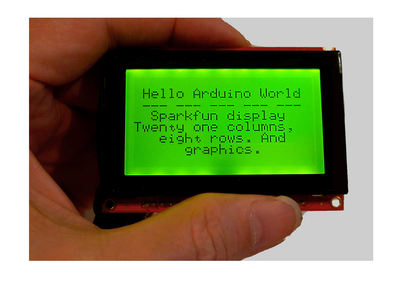
Below: An image of the Sparkfun product in operation.
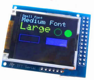 If that isn't quite what you wanted, maybe the TFT display from Hobbytronics will suit you? Color. Higher resolution. Very pretty! (Also driven by a simple serial data steam, "load" on host: Just one digital output.) Not a large display- just under 2 inches across... but only about $20/$30, and 160x128 (very small!) pixels.
The display can present text. Eight rows of twenty-one characters. They won't be "pretty", like text on a fancy modern smartphone... but the display won't cost what a smartphone costs, either.
You can update the text on the screen selectively... that is to say you can go to a particular character, or block of text, and change that... without having to refresh other parts of the screen to do it.
You can draw lines, boxes, circles. You can clear a rectangular portion of the display. You can plot or clear individual pixels. (So, with a little software, you can draw graphs, etc.) You can erase previously drawn stuff.
The essence of it is as follows...
You give the module power (5v will do. 6v ideal. Not more than 7v. You can "go fancy", or, if you're willing to be a little "sloppy", you should be able to get away with drawing 5v from the 5v powering your Arduino, Pi, whatever. (Be sure it is a full 5v... some USB supplies are a little under that, and the Arduino still functions, but you may find that the display flakes out at, say, 4.5v. There are notes on "doing it pukka" at the Sparkfun page. Not hard.)
And then you connect one output line from the Arduino (or Pi, etc. (Assume I say that every time I say "Arduino" in this)) to the display module. Send "stuff" down that line as a stream of serial data, and the "stuff" appears on the display. You send text as text, and there are commands to draw graphics.
In passing: It will Just Be Easier if you use digital line 3 for the output from the Arduino. It's not impossible to use a different line, but use 3 for now.
Easy! Well... mostly. I must admit I haven't tried ALL the promised features, and that I've had a few "issues" along the way. But I have no doubt that the unit would work just fine as a modest display for anything needing a display, demanding very little from the Arduino (or other driving "intelligence"). The one reservation I would make to that is that I think the update speed may be a little "slow". Nothing you'd care about in some applications, but it wouldn't, maybe, make a good screen to display what a radar system was seeing, for instance.
It may be worth the very limited "hassle" and "downside" of using the library Sparkfun has provided. I will turn to that soon. First, two things...
The world, sigh, is moving on from Windows XP. I haven't had the problem before, and I suspect it is a coincidence, but I had the very annoying and intermittent "collect2.exe: error: ld returned 5 exit status" problem while I was getting to grips with the Serial LCD Backpack. I was using an XP computer with the Arduino 1.8.0 IDE. I had "collect2" problems even when using the LCD unit in the very simplest manner, with nothing more than SoftwareSerial. (It didn't need to involve the SparkFunSerialGraphicLCD library.) As soon as I moved the work to a Windows 7 PC, running 1.8.2, the problems stopped. Throughout, I have been using a Sparkfun Arduino Pro Mini, 5v, 16MHz, Atmega328.
So... another "triumph" for Gates, and his "improvements". Sigh. N.B.: I didn't ALWAYS get the "collect2.exe" problem... but it came and (mysteriously) went. Life is too short to fight that sort of fight. (Read what's been written online about the problem before you ignore that advice!)
(Ironically, having written the previous paragraph, I then went on to use the device on my old XP machine for about two hours, writing the rest of this on that, and I didn't hit the "collect2.exe" problem again in that period! Which made my life much easier, as I could copy/ paste code examples directly from the Arduino IDE to the text behind this, without having to sneakernet them across from the Win 7 machine. Go figger. Not that I am complaining!!)
Update: Feb 2018 I was using a the vers 1-8-1 Arduino IDE, Win 7 computer, a Sparkfun Arduino Pro Mini (5v/ 16Mhz) and a Modern Device USB BUB II.... and all went very well.
(Doing It, continued...)
As I mentioned before, you only have three connections to make. I'll repeat them in a moment, but, as sometimes these pages are read by novices, I will cover a general point...
Unless you only ever work with one sort of Arduino, be careful when you start a new project. BEFORE you connect your Arduino, go into the IDE, click on the "Tools" menu item, and use the Board and Processor settings to configure the IDE to work with the hardware you are going to use. THEN you can connect the Arduino. And at that point you will possibly have to specify the port it is on.
Then put in at least a "skeleton" of what you what for the program for what you are setting out to do today, and compile it, and upload it to the Arduino.
You do all that BEFORE you connect anything to the Arduino! Step by step... always best. Why this "hook up, power up, program Arduino" before connecting anything else?
The GPIO pins on the Arduino can be programmed to operate as inputs or as outputs. If you have a pin programmed, from a previous use of the Arduino, as an output, and then connect hardware for "today's" project which is, in effect, an output from the outside world's hardware to the Arduino, it can be Bad For The Arduino!! (Very bad. Bad enough to fry the pin, or, less likely but not to be risked: The Arduino!)
So get the pins configured, as input or output, and then make your external connections.
For the "getting to know you" phase of working with the Serial LCD Backpack unit, you don't need any fancy connectors... a simple prototyping board can do the job....
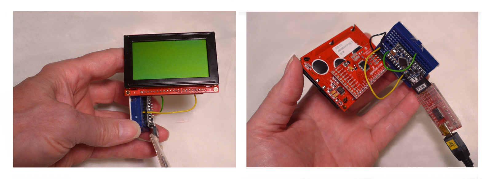
The left hand image shows the front of the LCD, with no power, no text or graphics being displayed. See the blue proto board, under my thumb? It is at right angles to the LCD module. And you can just see, though you wouldn't know that is what it is, the Arduino Pro Mini, edge on, to the right of the proto board.
Now look at the right hand image. The large red area is the back of the LCD module. It's four pins have been inserted into the last three columns of holes of the blue proto board. The Arduino Pro Mini is now seen easily. At the lower right is the ModernDevice "BUB" which is how I connect my Arduinos to my PC, for programming. Again, there's a pin/socket connection between that and the Arduino Pro Mini.
Moving on....
First, somehow or other, connect the unit's ground (GND) to a ground pin on the Arduino. (Black wire, in the images above.) Then connect the LCD unit's "Vin" to a source of 5v... you can use the Vcc pin of an Arduino Pro Mini. (Yellow) And lastly, connect the LCD unit's "Rx" (stands for "receive", not "prescription"!!) to the Arduino's (D)3. (Green wire.)
(Novices: Don't be confused by the old demon: An OUTPUT from the Arduino is going to go to an INPUT of the LCD unit. From the Arduino's point of view, what should go on the screen is output, something it sends. From the point of view of the LCD unit, the same stream of data, the same electrical signal, is received. It is input to the LCD unit. Clear? No, it muddled me for a while too. But that's how it is!)
That's it! Hardware done! The backlight should come on. If you watch it during the first second after receiving power, you will see the Sparkfun logo in the middle of the screen.
 (Unless the "display Sparkfun logo during boot" behavior has been turned off... it can be... Or maybe the contrast setting got disturbed. Both unlikely. Troubleshooting help for both on the Sparkfun website.
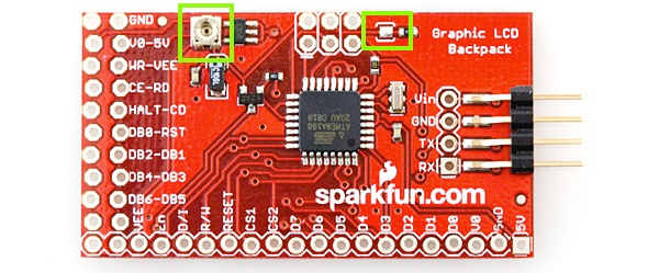
Contrast is adjusted by the tiny... quite sensitive... little pot on the back, in the lime colored square (added to illustration, not present in real life) on the left in the image to the right.) If the supply voltage changes, the contrast setting will need changing.
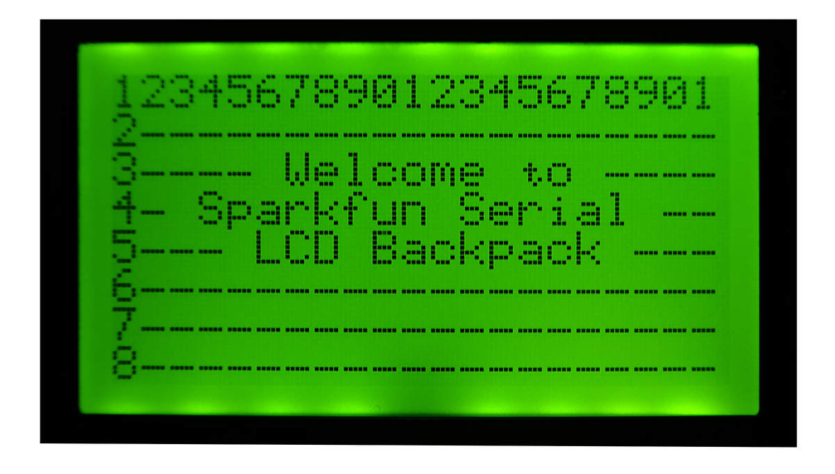
The following image is what you see if you run the program below it. Note: This doesn't use the library. It also shows you that the font is "mono-spaced", i.e. every character always takes the same space. AND it shows you that the display allows eight rows of text, 21 characters per row. This, remember, is the small version of the Serial LCD Backpack display unit. (I believe, but have not tested, that the large unit would allow 16 rows of 26 characters.)
Remember... the unit is also capable of graphics. (See below.)
Here, I am only going to show you a small taste of using the LCD unit without using the library. If you want to use it without the library, see my more recent page about this device, or see the "Ascii Commands" section in The Sparkfun Serial Graphic LCD Hookup guide. (My more recent guide also covers some "gotchas" not covered here.) And don't let the awkward text about non-printing character (decimal ASCII 124) which is the "escape character" to indicate that what follows is a command put you off too much. Nor the awkward text about generating some of the characters needed for ASCII commands. Do it all as done in the program below, where we send 124 and 0 to clear the screen, and life is not hard.
Read the material in the comments in the code, too, please...
#include <SoftwareSerial.h>
SoftwareSerial mySerial(2,3); // RX, TX
//We're not going to use line 2. I would normally "waste"
//  it, for "the simple life". If I needed "just one more"
//  INPUT, I would risk using line 2... but reluctantly.
//We NEED the serial output created by the above, and it
//  doesn't come in a "just create an output" version.
//I would NOT use line 2 for an output via other code
//  in the program.
//(You can change the lines used for the serial input
//  and output. Just change the "2" and/or the "3" in
//  what I put, above.

void setup() {
//This next not "needed"... but I think it is a Good Thing
//to have in any program. It sends a message to the
//serial monitor. Again, you don't "need" the message...
//but it costs little, and you may find it useful in
//various ways.

Serial.begin(9600);

//Now initialize the channel over which we will send messages
//to the LCD unit
 mySerial.begin(115200);
 delay(1800);

 Serial.println("SimpleSerialLCD, ver 27 Apr 17, started 26 Apr 17");
 Serial.println("Expects Sparkfun LCD-09351 on D3.");

 //Clear the LCD screen
 mySerial.print(char(124));//cmnd follows...
 mySerial.print(char(0));//Clear Screen
 delay(800);

 //The text in what follows is quite carefully chosen.
 //I suggest you try it exactly as presented, before
 //experimenting with alternatives.
 mySerial.print("123456789012345678901");
 delay(1200);

 mySerial.print("2--------------------");
 delay(100);
 mySerial.print("3---- Welcome to ----");
 delay(100);
 mySerial.print("4- Sparkfun Serial --");
 delay(100);
 mySerial.print("5--- LCD Backpack ---");
 delay(100);
 mySerial.print("6--------------------");
 delay(100);
 mySerial.print("7--------------------");
 delay(100);
 mySerial.print("8--------------------");


}//end of setup()

void loop() {
}//end of loop()
No prizes for subtle to the programmer of the above! Pretty "stodgy". But it shows the unit controlled without using the library.
Notice the delay statements after each mySerial.print. It seems to take a little time for the message to be transmitted, and/ or the LCD module processes commands a little more slowly than we might expect. It isn't "slow" in human terms, but you need to put the delays in, to give a little "breathing room" beyond the unimaginable pace normal inside the silicon. If you get gibberish at a point where you're expecting something different, the first thing to try is a longer delay after whatever the last thing to execute properly was.
If you choose to use the library... which is probably a good idea... a simple program would look like what you'll see in a moment.
I should first mention... as I have in funking addressing other issues!... that Sparkfun gives you some help with "libraries", too!
If you'd rather eschew the issues of libraries, you can just "talk" to the module directly with ASCII commands. I suspect that the library merely "wraps" the ASCII commands in a user friendly interface. As I said earlier, more recently I've written an alternative stand-alone introduction to this splendid text and graphics LCD display driving hardware which explores the "use ASCII commands" approach in greater detail. (It also covers some "gotchas" that I haven't gone into here.) The photos which appear on the page you are reading illustrate the things you can do either with the library or with the ASCII commands.
You don't have to go to GitHub to get the library, as you might infer from the Sparkfun guide. (Or maybe you do, "under the covers", go to Github, but the Arduino IDE makes it very, very easy...
Fire up the Arduino IDE. Invoke "Sketch/ Include Library/ Manage Libraries"
That should open a window with a bunch of libraries on offer. Put "serial LCD" in the "filter your search" edit box. That should collapse the number of libraries on offer to "Sparkfun Graphic LCD Serial Backpack by Mike Hord", and one other library.
In the "Sparkfun... Hord" entry's box, there should be a link for "more information". (My pc was online, which, for this stage is, I think essential... but not needed later)
Click the link, and a choice of versions should open up, and an "Install" button appear. Selected the latest version (1.0.1 when I did this), and click "Install".
It took only a moment. The screen flickered... but after the flicker, "INSTALLED", in teal, was added to the entry about the Sparkfun library, which hadn't been there before.
Close out of the Library Install process.
Now, if you invoke "Sketch/ Include Library", then in the section for "Contributed Libraries", you should see...
SparkFunSerialGraphicLCD
...which wasn't there a moment ago... and which you can now use in your programs. (It even put its files where I would have wanted them... the "Libraries" folder of MY folder for my Arduino program code folders!)
Whew! A palaver. Harder to describe than to do. And you only need to do it once. After that, the following should work!...
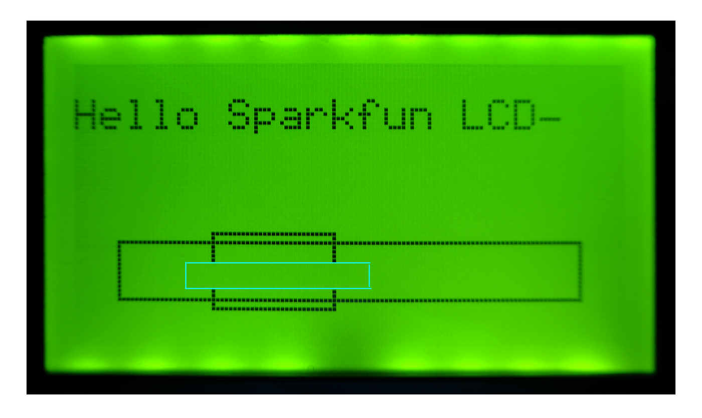
The cyan box does NOT appear on the LCD display! It is there to show you where I cleared an area of the screen with myLCD.eraseBlock(15,45,70,50); after drawing the two rectangles. The eraseBlock explains why the bits are missing from the vertical sides of the smaller rectangle.
I apologize for the fuzziness in this and some other images. ALL of the display was as bold and crisp as the "Sparkfun" in this image happens to be.
Besides doing text and boxes, you can do circles, or even plot individual pixels (or clear them). So, with a bit of software in the Arduino, you could plot graphs or draw pictures.
Again... there are important hints, tips and Things You Need To Know in the rems below. Note in particular the first two...
#include <SparkFunSerialGraphicLCD.h>
//Note: As above. Not as in the example on the Sparkfun page
//referred to below. (In the example, the "Sparkfun" was absent... at least it was, 20 Apr 17.
//Sparkfun moved quickly to correct that, when they were notified. But left
//the following. Maybe it is needed? But I don't think so.

//#include <SoftwareSerial.h> << This is PRESENT, 27 Apr 17, in
//example on https://learn.sparkfun.com/tutorials/serial-graphic-lcd-hookup
//in the "Arduino Library Example" section... and will STOP
//the program compiling.
//KEEP IT REMMED OUT, or remove it, when you are happy you don't
//need to be reminded not to be led astray by the Sparkfun
//example.)

const String strPrgmName("SimpleSerialLCD");
const String strPrgmVers("ver 27 Apr 17, started 26 Apr 17");

void setup() {
//This next not "needed"... but I think it is a Good Thing
//to have in any program. It sends a message to the
//serial monitor. Again, you don't "need" the message...
//but it costs little, and you may find it useful in
//various ways.

Serial.begin(9600);
Serial.println(strPrgmName);
Serial.println(strPrgmVers);

LCD myLCD;

delay(1200);//Wait for the one second splash screen to go by

myLCD.restoreDefaultBaud();//This should result in text on screen: "Baud restored to 115200".
//Note: All of the commands, as usual in Arduino work, are
//case sensitive. I.e. "restoreDefaultbaud" will not do. (Needs
//to be Baud, not baud.)

//You can insert a myLCD.clearScreen(); here, which will
//"erase" the response from the module, confirming baud rate
//reset. It isn't essential. (See the Sparkfun pages for a way to reset the baud rate
//to the default which works when you are unable to send
//commands. You won't be caught in the obvious Catch-22!

myLCD.clearScreen();

//Next takes a significant time to appear for some reason,
//even without the myLCD.nextLine();
myLCD.nextLine();
myLCD.printStr("Hello Sparkfun LCD");
delay(100);
myLCD.drawBox(10,40,117,53,1);//long box
//drawBox args: x0,y0,x1,y1, then a parameter which is supposed
//   to determine whether box "drawn" in background
//   color or foreground color... but -1,0,1 and 255 all
//   seem to result in "draw in foreground color".
delay(100);
myLCD.drawBox(32,38,60,55,0);//short box, slightly to
//right and below first box. If both can be made to draw,
//and the right value found for "draw in background found,
//"gaps" SHOULD appear in the lines of the long box when
//this one is drawn after because this is SUPPOSED to be
//in "background color"... but doesn't seem to be. Sigh
delay(100);
myLCD.eraseBlock(15,45,70,50);
delay(100);
}

void loop()
{
//nothing in loop
}
Where you see "LCD myLCD;" above, Sparkfun had "LCD LCD;"... which "works", but I think adding something to the name of the object you are instantiating helps keep classes and instances distinct. Not that elsewhere, Sparkfun had things like LCD.nextLine(); which had to be changed to myLCD.nextLine(); because of my earlier tweak.
The little programs I've shown you above are trivial, just meant to give you some of the basics. Don't let them make you think the device is trivial.
It would be a relatively small project, for instance, to set up a home weather monitor (with a few extra features), the monitor built in an Arduino with this display for reporting the data to the user. The display could look like...
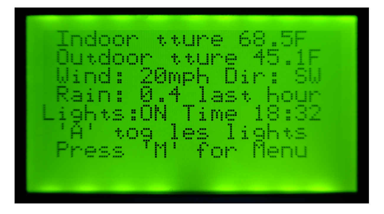
(The actual display I was photographing was crisp with good contrast everywhere. All of it was like the "20mph". The fuzziness at the ends of lines in particular is just an artifact of my amateur photography.)
The mocked up display is telling the user indoor, outdoor temperature etc. Also, on the 5th line, you see "lights: ON". I'm imagining a large house in a remote location with some security lights which turn themselves on at dusk. The user can turn them off again... or on early... by pressing the button (not shown), beside the display, marked "A".
In my imaginary system, there are other buttons, one of them marked "M". Press that, as prompted by the last line on the usual display, and the display would change, with some text to remind you what other buttons would do.
None of that is hard... but none of it is really the issue, here. Here I just want you to be aware of a neat little device... not perfect, but perfectly capable of making a contribution to a project!
The search engine merely looks for the words you type, so....
* Spell them properly.
* Don't bother with "How do I get rich?" That will merely return pages with "how", "do", "I"....
Please also note that I have two other sites, and that this search will not include them. They have their own search buttons.
My site at Arunet.
My Sheepdog Software pages, another of this page's editor's sites.
Here is how you can contact this page's editor. This page, and the software it references, ©TK Boyd, 8/2015.
Tried to test page for compliance with INDUSTRY (not MS-only) standards, using the free, publicly accessible validator at validator.w3.org. (Two unknown attributes due to Google+ button.).. but defeated by the non-compliant code in the listings.