 Recommend to StumbleUpon
Please note: This page will not always be 100% up to date.
At the time of writing (26 Jan 18), assembled, "working" instances of the first two versions of PCB 269 exits! And two further copies of that version of each PCB are on hand.
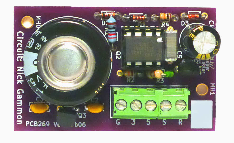
At 26 Jan 18, the current version of PCB269 is "v17b28". (Use what is in the silkscreen on the board, near the supercap. (Components' side.)
v17b28 "works"... but "better", if a trace is cut! (See PCB269-SolarWBackup-Versions.htm), and MAY be sending reset signal EVERY dawn, not just dawn-after-Vout-got-too low.
I know what I want to do in next version, another "small step forward" version... but don't know when I'll get to doing it. I doubt I'll create more copies of v17b28... I have two spare, unpopulated, new boards at 26 Jan 18 which you could use if you want to start with PCB269 NOW.
At the time of writing, I also have small stocks of most of the components for the board, including a "ready to use" ATtiny85 for one instances of PCB 269. (The ATtiny85 provides the circuit's watchdog feature... and if you don't need that feature, yet, the board works fine without the ATtiny.)
PCB 269 is an implementation of a circuit by Nick Gammon. It is for providing power to low demand Arduino (or other) systems. There's a "battery" (supercap... avoids the evil nature of lipos) to carry the system over times with no sun. There's a watchdog to break lockups which can arise from slowly rising voltages. The PCB 269 main page gives you the details.
Getting one: *IF* you don't mind supplying your own "bits and pieces" (although I MAY be able to help with some), and are willing to risk being "stuck" with TWO PCBs... though if I get a second order in time, I'll let you buy just one) I'd be willing to supply the PCB at this stage. Cost including p&p to UK or US address, airmail: $14 for two boards, $10 for one. Maybe a little less, if I'm able to avoid international mail in your case. Payable by Paypal. If you are sure you want to order at least two boards, and pay by PayPal, contact me, so I can tell you current situation. (Parts avail, shipping times, etc. Include where you want them sent (at least what country) when you enquire... I will order boards upon receipt of your payment, send off when I get them. Between ordering and receiving, orders usually take less than 2 weeks. I MIGHT, of course, have some on hand.) At the moment, I can't promise to supply an ATtiny85... programmed or otherwise. I will TRY to have some (programmed) available. It will all depend on demand, and on whether you're prepared to wait for it. If you don't want to face obtaining/ programming the ATtiny, it is not out of the question that I would do one for you. I just can't promise to do "right now". On the other hand, if you are an intermediate Arduino/ hardware person, I heartily recommend the ATtiny to you. It isn't hard! (Well... not too hard, once you get started.)
Great news? Not expensive! Probably about $10 for "bits and pieces", including the PCB. To this, you need to add a supercap... $5?... and a solar panel or two...$5?. Plus of course whatever it was you wanted 24x7 power for.
So much for the good news!
The bad news? At 28 Jan 18, board version 17b28, I find that when the ATtiny is on the board, even before you draw power to do something useful, if Vin is interrupted when Vout can initially supply 4.83v, that falls to 4.0 in only half an hour, and to 1.97 in 90 minutes. Hardly the "through the night" expected! (And that's with a 1F supercap... twice what Nick was using.) An Atmega 328 would still be running... if you don't allow anything for the power it would have been using!... but only just.
Nick is a very credible, experienced Arduino user. I fully expect that the low power capacity I am seeing is down to a simple "boo-boo" in my work to implement his project. If you could help me find it, I'd be delighted! I suspect it is somewhere in how I've programmed or configured (fuses) the ATtiny... I am new to these wondrous beasts. And the board hold power nicely when everything other than the ATtiny is present. (It is only there to provide the watchdog, by the way. The board already works fine to save, massage, and deliver power if you leave the ATtiny out.)
I'm just a hobbyist. I don't look to make money out of this, nor am I geared up to be a fully professional distributor. I do hope to help fellow hobbyists, but this isn't "my day job". And the whole thing is a bit "chicken and egg". I'm not going to order a dozen copies of the PCB to have a good stock on hand, when I've had, so far, no indication that one person wants one, let alone a dozen.
Bottom line: SERIOUSLY interested in BUYING bits... write me! I'll give you a personal and up-to-date update. Major suppliers or contributors to forums known to me, who could test, evaluate, etc... I would supply you a free copy of the board, and what parts I happen to have, on a promise of evaluation work, and return or purchase of the board and parts on conclusion of the work.
See PCB 269's main page for the "definitive" "word" on most issues. This page is meant (and working towards!) being just about stock levels and ordering.
I ran out of energy for this. Not permanently, I hope, but for a while. I couldn't think why the supercap either wasn't charging (I don't think it was that) or didn't seem to have the capaicity I expected. (More likely that. I don't know a lot about a number of related issues... I may not have tested capacity or understood resultsRoughParts correctly.)
The "good news"?? This part of the problem is, I think, "upstream" of the "clever" stuff in "the red/orange" section, the watchdog/ reset pulse section. (As set out on PCB 269's main page). Get the issues of charging the Supercap (and getting a sensible amount of electricity from it during dischage), an I'm your man!! to "fix" problems in the red/orange section.
The following wasn't really meant for "publication"... but is offered as "better, I hope, than nothing. Make what you can of it!!
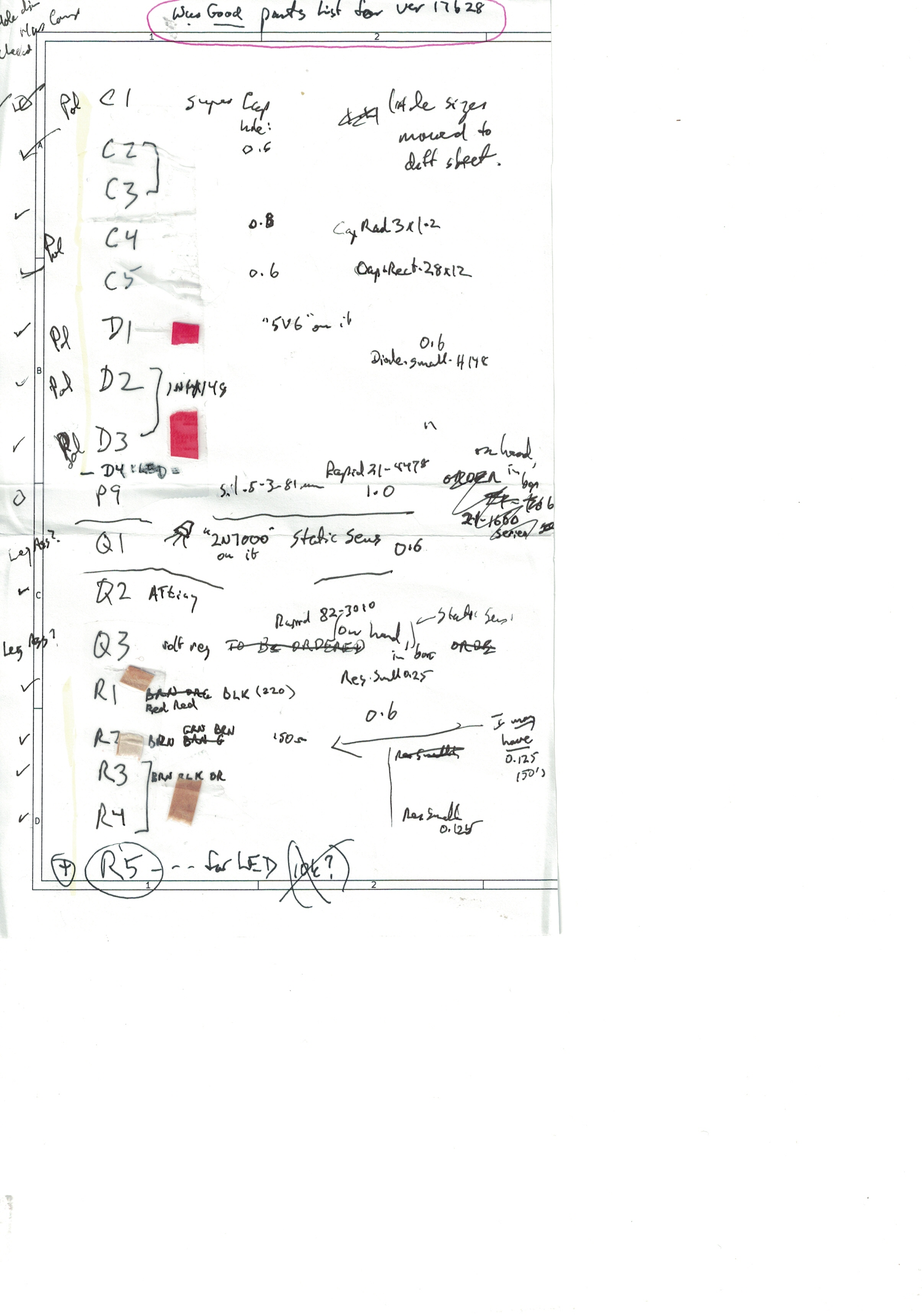
While I'm posting not-ready-for-publication-messes, here, for what its worth, is a scruffy, possibly not accurate, parts list for you to build on...
Two units have been assembled. One for each of the first two versions of the board. The first was quite extensively tested, and the second has had some tests. Works as expected. Exhaustively tested, under all scenarios? No, of course not. But basic "stuff" seems to work as advertised. (See the 'Old Versions page if using a board from before the 'current' version.).
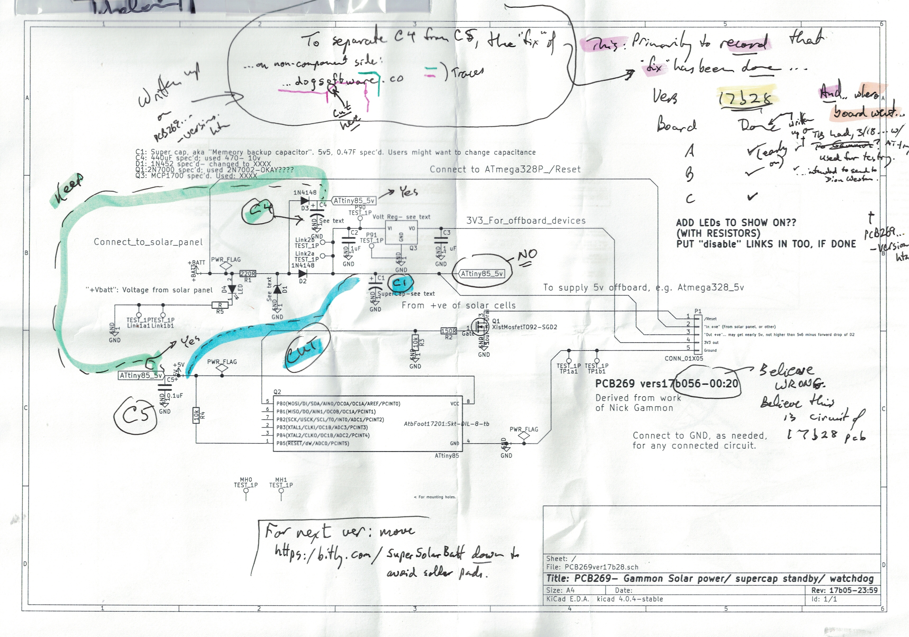
At 26 Jan 18, I've made a serious start on a third version of the board... it will probably be called "vers 18126" I just don't have time for that just now. The second version (v17b28) "works"... it just needs one track cut to be "perfect"... as far as I know so far! (AND v17b28 (and the first version) resets the powered device EVERY morning, not just on mornings when the supercap ran out of "juice". Deal-breaker? Not! Maybe a desirable feature!)
The biggest "problem" with this lovely design: It won't power very much "all through the night". In fact, so far, I've not got it to power very much over an interruption of Vin of more than about 10 minutes. But there are several avenues which can be explored to see if this can be "fixed". Or maybe my hopes are too high for this simple, elegant, and ROBUST "answer" to getting power with a public power supply is not available. I only designed the PCB. The circuit came from Nick Gammon, whom all Arduino enthusiasts should learn about, if they don't know of him already. He had the circuit driving an optimized Arduino, taking weather sensor readings, and sending them to a base station over a radio link. PCB 269 implements only the power supply section of his work, but the page cited a moment ago goes into the details of the rest, too.
Also remember that if you "just" want a little circuit to see low demand systems across short dropouts arising when a public power supply fails and a standby generator kicks in, then PCB 269 is working well enough already!
Each version of the PCB has been marked with a version ID. It is a date string in the format yymdd, where "m" is 1-9 for Jan-Sept, or a,b,c for Oct, Nov, Dec. The date string is prefixed with "vers", "ver" or "v".
(This merely the highlights, but comprehensive as to existing versions. See my 'Versions of PCB269 for full details of old versions of the board. At 26 Jan 18, there's only one "current" board... i.e. at 1/18, there are no "alternatives".)
Ver 17b06: Three copies. Will probably never be more. "Ok", except for the silkscreen for Q3 being "backwards". (For an ST LE33CZ-TR)
v 17b28: Three copies. This was just a minor "baby step" forward. Tried to fix Q3 problem. Some testing done. Discovered a connection that shouldn't exist. (Was present in v17b06, too.) (In v17b28, easily broken. Probably ditto in v17b06) I think there's a minor problem with one of the "isolating" links. (L1 or L2). May be doing reset EVERY dawn. But seems, mostly, to "work".
None of the things that go in this board are terribly expensive, but don't you hate having to place an order with a supplier for one resistor?
Suppliers, of course, are not charities. It is only reasonable if they put a p&p charge on small orders. If there is sufficient interest in PCB 269, i will be quite happy to make up and supply kits of parts. I can already help my first few "customers". Eventually, if the interest is there, I will work up something more satisfactory. For the moment- email me, tell me your wants, and a bit about how much experience you have (how much hand holding you will need) and I'll tell you what I can do at the time you email.
The programmed and fused ATtiny85 for the watchdog feature is likely to be the biggest problem for both of us. If you can "deal with" sourcing and programming and fusing your own, it will be a big help. I do, present time, have "one and a half(!)" available, though.
I would be, by a wide margin, most happy with payment by Paypal, "gift to friend", from a bank account. Yes- it leaves you (and me!) bereft of some protections. We're not talking a lot of money here, people! (I'd consider other variations on the Paypal scheme, especially if YOU paid the charges, if that's an option.) Or a check/ cheque, US dollars or British pounds. Not so good, but possible. Again, I am particularly happy to consider variations on my proposals for people "know to me" from their presence in forums, especially the main Arduino forum. In any case... you are the "customer"... in a limited way. Tell me what "works" for you?
When I went to order parts, to keep my life simple, I made some substitutions. I can't promise that they were valid substitutions! As I mention elsewhere: you are the final inspector.
1) For D1, a 1N752 was specified. I used a BZX55C5v6. (You can get the spec sheet for this, and many other things, from RapidOnline.com's website. For part numbers, see "Parts list" section (which is in a separate page, which opens in a new window or tab, if use the link. Just close that to return here.)
2) For C1, the supercap, I used a 1F, 5v5 Panasonic EECF5R5U105. Note that the pads on the PCB have been done to facilitate adaptation for whatever supercap you decide to use. I'm not sure that the voltage rating of the one I used is as high as it should be for this circuit.
This next section became recursive. You can skip my manic ponderings, and come back to them later, if you wish?...
Very late in the day, I discovered a disturbing little line in the datasheet for the supercap I had purchased. It recommended "1 mA or less" as a typical discharge current for the supercap. I couldn't find a "max safe" rating. "I read on the internet" that supercaps can typically endure "high" charge/ discharge currents... so I'm hoping that my supercap is actually more capable that the rather short datasheet would suggest. If you go supercap shopping, I hope you can find one with a stated greater current limit. Or that the circuits you want to power use very little current!
If you read the fine print in the rather limited Panasonic datasheet, you find: "Recommended discharge current: 1mA or less"... but that qualified with a footnote saying "The recommended discharge current is a reference value. Please design your equipment (circuit) in consideration of IR drop."... the IR given in the datasheet as "less than 30 ohms at 1 kHz." I think they are saying this thing will provide high currents unless there is resistance in the external circuits. Fine. But without a max power dissipation rating, we're somewhat in the dark as to how low we can let the external resistance be before problems arise. Panasonic see the supercap as a good source of voltage to back up memory circuits... fine! And THEY would need little current. But what about our wants? I hope you have better luck in your supercap shopping!
Further work on supercap selection: I have never been so frustrated in searching for a datasheet!
"Supercap" is a bit of a nickname. "Electric double layer capacitors" may turn up things that supercap won't.
I finally found one for a supercap that "came clean" on permissible discharge, thank you Farnell! Their VEC6R0 504QG - Supercapacitor, 0.5 F, 6 V from Vinatech costs £5.99 (Nov 17, plus p&p, etc) and the 6v rating helps make it "good" for PCB 269, even if the "mere" 0.5F is a little disappointing. (It should be noted that supercaps, unlike, say, lipos, discharge in a linear manner... they don't maintain their voltages for large parts of the discharge cycle, and then drop suddenly.) The datasheet says that this supercap may be discharged at a rate of 1A, and suggests that would bring the voltage on the cap down to 3 volts in one second. Not an operating scenario we are looking for! But reassurance that our much more modest discharge current wants are acceptable to the device!
MORE on supercap shopping!... Hurrah... the Vishay datasheet for their 196 HVC ENYCAP supercaps gave me "max discharge current"s (MDC) of 25mA to 3A for their range, along with recommended charge currents. The MDCs varied with the capacitance of the supercap in question. They come in 5v6 and 7v0 spec'd versions. As discussed elsewhere, 5v6 may be sailing a bit close to the wind, but may be okay. 7v0 will be more expensive... but you can get a whopping 15F, 7v0 Vishay MAL219691215E3 from RS Components for £11! If I read the datasheet correctly, the max charge current for that is 50mA, max discharge 70mA... but with this, we encounter a new issue: "Lowest discharge voltage". "Permanent operation below [4v0] is not permitted"! What happens if you DO discharge further? Could another zener diode somewhere "fix" things? Sigh! (There are multiple ideas here. But if you "disconnect" the supercap unless the voltage it provides is at least 4v0, there may be implications for how the watchdog does its thing. (I haven't thought this one through yet, but it would need thinking through. Or maybe I just worry too much?)
3) For C4, I used a slightly larger capacitor, 490uF instead of the specified 440uF.
4) My "most serious" "mistake", as far as I know: For Q3 (the regulator supplying 3V3), I used an STLE33CZ-TR... because it was "the one I could get"... instead of the specified MCP1700. Someone who knows about these things reviewed my choice, and, no promises, thought it might be okay, though a little less efficient. I.e. the MBP1700 wastes less electricity, might make a circuit slightly better at making it though a "no sun" period than the circuit using the regulator I used. See further comments in "my page on the versions of the board". (That page will open a new tab or window. Just close it to come back here.)
Here, in one tidy place, a list of what you need. With part numbers, if you choose to order from RapidOnline.com's website, which happens to be in the UK. If you compile a similar list for a major supplier for customers elsewhere, it would be much appreciated if you were to email it to me, for inclusion here.
I am hoping, eventually, to offer kits of parts.
You need....
1) The PCB. Eventually, likely to be available from OSH Park. For now, email me if you are willing to suffer along with other early adopters. If you have a reputation at forum.arduino.cc, or similar- so much the better. Tell me your forum name in your email. (I am "tkbyd", there.)
2) A programmed (including some fuses) ATtiny. I am using ATtiny85s. The board has a place for an 8 pin DIL package. I don't know of a source of programmed ATtinys at this time, but programming your own, and setting the fuses, is not, it seems... though I've yet to try it!... hard. The devices cost very little... less than $3.
3) Hardware:
a) A socket for an 8 pin DIL.
b) A 5-way block of screw terminals for attachment to a PCB-
RapidOnline part number 21-4478 (65p... all prices excl p&p, and good at 11/17)
(Called "P1" in first version of board, P5 thereafter.)
c) (From the boards "v17b28") Optional: 2 pairs of 0.1" separated pins to make two selectable links, L1, L2.
d) The solar panels! (If you are using solar as the ultimate source of power. PCB 269 can also be used as a "bridge" to carry circuits across switch-overs from mains power to generator backup.) I can't give you as much advice as I would like on this front. 6v panels would seem to be "right". Which is about as helpful as asking a bookseller for a "red" book! (More on this later, I hope! For now, buy something cheap via eBay or similar, promising 6v!) The panels used with the original of this are no longer available, but I'm sure replacements abound. They cost $25, and were described as follows...
    Power Output: ~6V @ 1W (~160 mA)
    Output Type: DC Voltage
    Dimensions: 100mm / 3.94" x 198.43mm / 7.81" x 0.77mm / 0.03"
    Operating temp range: +32 to +158°F (0 to +70°C)
    Weight: 27.93g
4) And the rest.... (Listed alphabetically by part reference)
(Don't overlook, listed, with details, a moment ago...
a) Socket for an 8 pin DIL.
b) Five-way block of screw terminals
c) Optional: 2 pairs of 0.1" separated pins to make two selectable links, L1, L2.
d) Solar panels, or other source of Vin.
C1: Supercap (See substitutions)
Spec'd: 0.47uF. I used 1 F, 5V5.
RapidOnline part number 11-2170 (190 (i.e. £1.90))
(See discussion here of D2, D3) See also notes in the "substitution" section. The Rapid Online 11-2170 may be "special" in not being suited to "high" discharge currents. (The datasheet recommends "1mA or less" as typical discharge usage. Remember: C1 is going to be supplying the current flowing through the (nominally) "5v" output of PCB 269, and powering the ATtiny, and supplying the voltage to be regulated down to 3v3.)
C2, C3: 1uF caps
RapidOnline part number 11-3425 (4p each)
C4: Capacitor (electrolytic)(See substitutions)
Spec'd: 440uF. I used 490uF.
RapidOnline part number 11-3513 (6p ea.)
C5: 0.1uF cap
RapidOnline part number 51-8686 (20p)
D1: Zener diode (See substitutions)
Spec'd: 1N752. I used BZX55C5V6
RapidOnline part number 47-3016 (6p)(< (price, in pence, i.e. hundredths of GBP (£))
D2, D3: 1N4148 diode
RapidOnline part number 47-3309 (1p ea)
(Discussion at https://jeelabs.org/2012/05/14/forward-voltage-drop-on-a-diode/ suggests that a BAT43 might be a better choice next time. Thoughts welcome! Note that this would mean voltage applied to supercap would be very near the maximum rating, for the "5v5" supercap at one time spec'd elsewhere, here
(Optional) D4: small LED
(From v17b28). To indicate power being available from the solar panels, or whatever primary source you are using.
Q1: Mosfet transistor 2N7000
RapidOnline part number 47-0180 (10p)
Q2: ATtiny85 microprocessor
You will need to program it, and set fuses. An ATtiny85 would be "perfect"... others may suit... if in 8 pin DIL package.
RapidOnline part number TBD... I bought my first ATtiny's from Hobbytronics.co.uk
Q3: 3V3 voltage regulator (See substitutions)
Spec'd: MCP1700. I used ST LE33CZ-TR
RapidOnline part number 82-3010 (67)
Board v17b28: Beware error in silkscreen- see note in "my page about old versions of the board". (That page will open in new tab or window. Just close that to get back here.)
From board v17b28, alternate pads exist, to allow easy use of originally specified MCP1700. (It has different pinout.)
R1: 220R resistor. A 0.25W resistor should be used. Remaining can be 0.125W, and PCB expects these.
RapidOnline part number (TBD)
R2: 150R resistor, 0.125W
RapidOnline part number 62-0350 (1p)
R3, R4: 10k resistor, 0.125W
RapidOnline part number 64-0098 (1p each)
(Optional) R5: resistor, 0.125W
(From v17b28)- Something suitable for LED D4. Simply indicates power coming into the board. Will "waste" a little power while power is coming in, but draws no power when the system is running from the supercap.
Eventually, the idea is to make the boards "freely" available. I'm not going to try to "make money" on this. I might initially release it via a Kickstarter project, or in partnership with, say, Sparkfun, ModernDevice, Hobbytronics.co.uk (if any of them would take it on!!) or similar... but only in hopes of bringing the board to a wider audience. Nick released the circuit without asking for any reward. My board merely implements his circuit, so it should be "free", too. Eventually, I expect that you will be able to order copies of the board directly from OSH Park, at cost. But I hope also to get in place an easy way for you to obtain a "kit of parts"... including, optionally, a programmed ATtiny, for those who want the optional watchdog timer reset part of the design. I say "free"... but that doesn't mean that I won't make a charge to cover my expenses, and give me some compensation for the overheads of keeping the parts on hand, my time "picking parts" to assemble the kits, and postage. Duh. Sorry!
Getting one: Even if I have no PCBs on hand, *IF* you don't mind supplying your own "bits and pieces" (although I MAY be able to help with some), and are willing to risk being "stuck" with TWO PCBs... though if I get a second order in time, I'll let you buy just one) I'd be willing to supply the PCB at this stage. Cost including p&p to UK or US address, airmail: $14 for two boards, $10 for one. Maybe a little less, if I'm able to avoid international mail in your case. If you are interested, contact me, so I can tell you current situation. (Parts avail, shipping times, etc. Include where you want them sent (at least what country) and how you intend to pay when you enquire... I will immediately order boards if we can agree terms, send off when I get them. Between ordering and receiving, I usually wait less than 2 weeks. I MIGHT, of course, have some on hand.)
It has to be said that the supercap solution will not, easily, give you a lot of battery backup. (For more on this, see my "Testing PCB 269" page)
The PCB discussed here, based on the Gammon circuit, gives you a power supply suitable for charging by a solar panel (though that's not the only option). (This voltage is called "Vin" in this discussion.) It has a super-cap to get you through the night, and a watchdog circuit to ensure smooth re-starts after instances of too many hours of too many clouds. There is an optional 3v3 output, regulated, and a second output to run a "5v" Arduino, not regulated. (This voltage is called "Vout" in this discussion.) (The Atmega 328 will run on voltages from 1.8 to 5.5) The limitations? The circuits you power must not draw much current... unless you can solve the issues relating to "big" supercaps, and unless you buy big solar panels. (But you can start with a $5 "wonder" from eBay, though!)
Another use of this circuit is to provide a "bridge" to get a system across that tiresome "gap" which some people with unreliable public electricity and emergency standby generators. When the public supply fails, there is often a brief moment of no power before the generator takes over. And another dropout when public power is restored. PCB 269 would be good for bridging the gap... you would just use an ordinary USB charger, powered by the public/ generator supplied volts, to supply PCB 269's Vin. For such short periods without power on Vin, you could power a more current hungry system without having Vout from PCB269 fall too low.
The circuit in question was originally designed to power, 24x7, without human assistance, a small data collecting system, which sent the data collected over a radio link to a "base station". Adding the radio-equipped Arduino would add about $15 to the project, at a rough guess. (All the details of that, too supplied at Nick Gammon's page.)
Nota Bene: I don't know much about some important issues relevant to this circuit, so please be particularly aware of my usual disclaimers. In particular, I have almost no experience of supercaps, and one is at the heart of this circuit. The good news is that the circuit was designed by someone who knows a lot. All I did was implement the circuit in a PCB. But along the way, I've made some substitutions, perhaps poor ones. (You can reverse my substitutions easily enough, if you can source the parts! Or if I buy some in, as I hope to.)
Be sure to read the "I read it on the internet" bit on PCB 269's main page about things you need to remember when working with supercaps.
You are responsible for any consequences of using what is on any of my pages!
Please get in touch if you discover any flaws in the board, or any ways to go wrong. How are using it would also be of interest.
I would welcome news of any use you put the PCB to... especially if it comes with a photo, and permission to mention here. By all means give me with that any website, blog, etc, you want publicity for.
If you found this of interest, please mention in forums, give it a Facebook "like", Google "Plus", or whatever. I've almost given up writing these pages, because it seems they are seldom read, and of course not every reader will use them... so... is there any point? If you want more of this stuff, help!?
Click here to visit my main homepage where you
can explore other areas, such as education, programming, investing.
![]() Page tested for compliance with INDUSTRY (not MS-only) standards, using the free, publicly accessible validator at validator.w3.org. Mostly passes. A few "bad attributes" due to Google+ button, etc.
Page tested for compliance with INDUSTRY (not MS-only) standards, using the free, publicly accessible validator at validator.w3.org. Mostly passes. A few "bad attributes" due to Google+ button, etc.
....... P a g e . . . E n d s .....