I will show you how to get started with ATtinys in a moment... after, I hope, whetting your appetite with information about what an ATtiny is.
If you haven't (yet!) used an Arduino, that might be a good place to start. But you don't need to "work" there long before you are ready for the wonderful ATtiny, so, onward with ATtiny matters!...
The term "ATtiny" covers a family of small microprocessors. For the rest of this essay, I will be talking about one in particular, the ATtiny85. Much of what I'll say about that ATtiny applies to other members of the family, which come in various shapes, sizes, flavors.
An ATtiny is a computer, if you will grant me that a computer is...
Forgive me being a bit dogmatic, but the above does define a computer.
And, by that definition, the ATtiny85 is a computer... all in a chip costing about $3 and only having 8 pins...
For $3. Wow.
If you programmed one to turn on an LED when you pressed a push-button, you would need....
- A voltage source... a battery would do, 2.7 to 5.5v... so three AA "batteries" in series ("cells", more accurately speaking... MAKING a "battery" when connected together) would be ideal. Or you could power it with a USB charger, or off of a USB port.
- The push button. Nothing fancy.
- The LED, and a resistor.
- Some wire. (Well, I couldn't leave the list so short, could I??
That's ALL you would need! (You'd probably want a breadboard, too, I suppose, to make hooking them up easy.)
No crystals. Nothing "fancy"!
Don't be put off by the simplicity of my example. The ATtiny can do MUCH more than create a completely over-engineered doorbell! But I wanted a specific example of "a thing you could do", to be grist for the mill of this essay.
According the excellent page from some MIT people, "HighLowTech", the following Arduino commands are supported. (HighLowTech also mention a "big brother" of the ATtiny that I expect I will be playing with, too! (The 44 or 84... both programmable by the same software, according to the page cited.)
    pinMode()
    digitalWrite()
    digitalRead()
    analogRead()
    analogWrite()
    shiftOut()
    pulseIn()
    millis()
    micros()
    delay()
    delayMicroseconds()
    SoftwareSerial (has been updated in Arduino 1.0)
Diversion! If you want a break, you might be amused by another page about ATtinys, written more informally. (Not necessary to following what the page you are reading is trying to do. If you click the link, it will open in a new tab. Just close to get back here.) (Bit from that: "So! He toiled late into the night, his eyes burning with love and from the fumes of solder smoke. For her he would put his wizardry to work. At the wave of a hand would write songs of adoration in the air with nothing but light. The runes of power, all typed out in the proper order, would be held by a ATtiny. A CR2032 coin cell provided the magic pixies which would march to its commands...." (Click on the "was wooing" bit to go from the write up to the details of the project.)
I admit... you need a little more, if you want to put the program into a "blank" ATtiny... but nothing fancy, nothing you don't probably have already if you've been an Arduino hobbyist for more than a few weeks. No "stuff", and not a lot of software or knowledge. (And the software is free!)
Why has no one been shouting "ATtiny" from the rooftops? The ATtiny85 came out in 2005!! And I only came across them in 2017??
Anyway... once I went looking, I found the nice people at hobbytronics.co.uk had a little ATtiny tutorial that gave me that "I can do this" feeling. And I was right. And what they published was most of what I needed! (For programming the ATtiny. If you do that, you will soon be wanting to "program the ATtiny fuses". That's easy too. I'll show you what you need.)
Most of what follows is just ONE approach. Another, from a very good source, is written up in a post about a ATtiny programming with SD cards system.
To program one, you just need...
A PC with the ordinary Arduino programming IDE.
An Arduino that can, from time to time, be hooked up (six wires!) to the ATtiny you want to program.
Some "extra stuff" in your Arduino IDE environment... I'll explain. It's nothing more than the sort of thing you'd "add", and you add it the same way, to set your IDE up to program something other than a standard Arduino. To program a Teensy or ESP8266, for instance. (They're two nice systems, by the way... I've written about the first, and used the second quite a bit... it was a shock to discover I haven't written something to say how great the Teensy is!)
Once that's in place, you program the ATtiny as if you were programming an Arduino. You have to look at what's hooked to your PC to tell the difference! (Details later.)
Above, I've tried to persuade you to try the ATtiny85. Now I will go into more details about what you'd have to do.
Usually, I work "from the ground up". This time, I'm going to tell you about where you WILL be, and THEN go back, explain how to get there. First I'll do it in respect of programming ATtinys. Then I'll do it in respect of doing things with their "fuses".
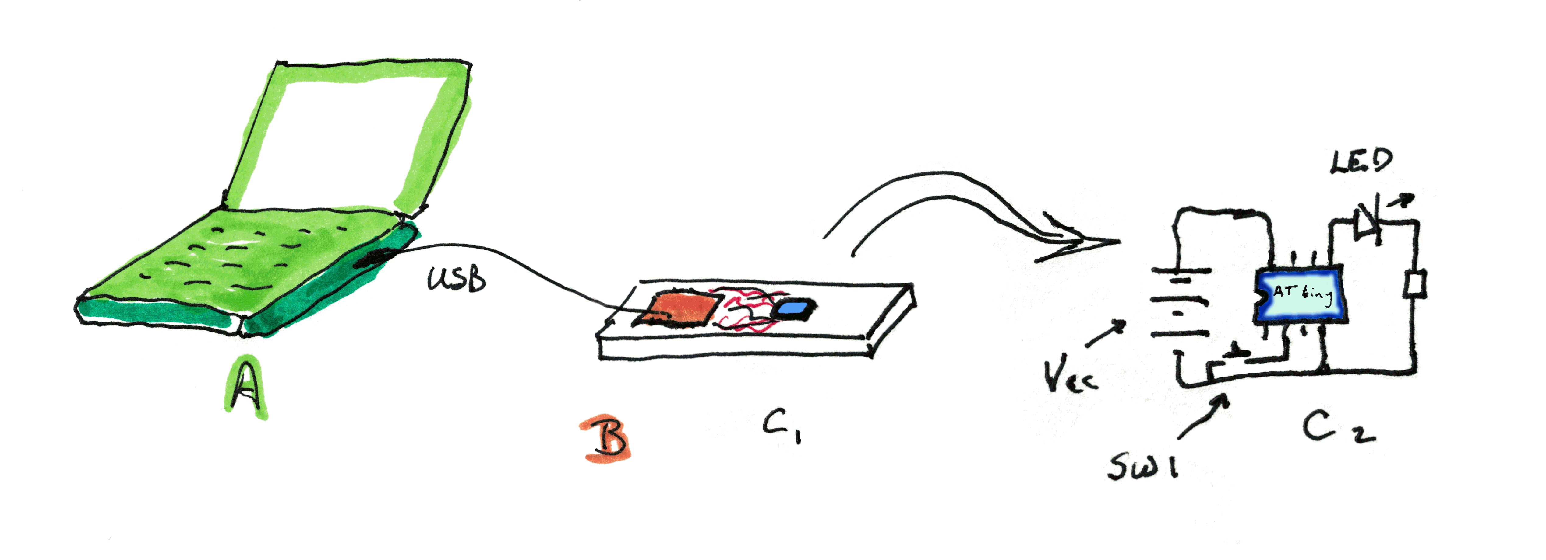
The picture above shows....
("A", green) An ordinary PC, anything will do. In it: The ordinary Arduino IDE, with one unremarkable "add on" (I'll explain it later.) I'll call this "the big PC" from now on. Connected to...
("B", red, and "C1", blue) A little breadboard, carrying an ordinary Arduino (ATmega328 or higher)... I happened to be using an Arduino Pro Mini ("B")... and an ATtiny ("C1"), connected together with a few wires. The little blue bit is "C1", the ATtiny being programmed.
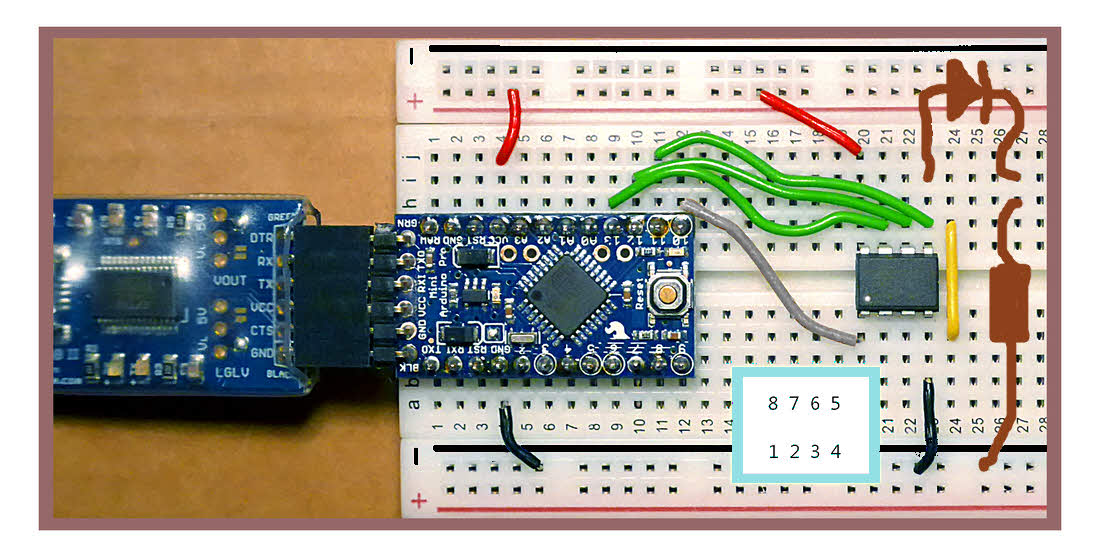
Below, I've done a picture of B and C1 in real life for you. Plus an indication of an LED and resistor I want on the board at this time. Sorry the LED and resistor are so crude!
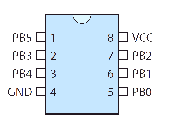
The white dot on the ATtiny, and the small inset panel with digits giving the pin numbers of the ATtiny show you which way "up" it must be inserted in the breadboard.
Rather late in the day, I realize I made an unfortunate mistake when choosing my color scheme. The blue bits in the "real life" image are the Arduino (the right hand blue bit) and its USB serial interface (on the left). They should be red, to match the my drawing's color scheme. And the ATtiny, black in real life, is what's shown in blue in the drawing. (The yellow wire is there as a guide to where the ATtiny goes. Remember: This is "the programmer", and the ATtiny you see in it is just one of many that will "pass through" this circuit.)
The circuit is the same as that suggested in the Hobbytronics tutorial; I've just used a single bread-board, for tidiness's sake.
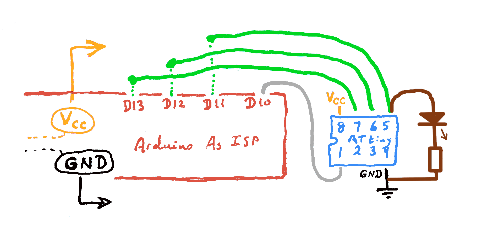
And, though maybe it is overkill?, here are the details of "B"/"C1" again, as a diagram. (Colors consistent with sketch at top of page, this time!)
Continuing the story of the "overall" picture, the prettier one, further up the page...
(C2: blue) The same ATtiny, later, removed from the breadboard it shared with "B", with a few bits and pieces connected up to it. This is the ATtiny in its final deployment.
(Do not, as you follow along in your head, connect the cable between big PC ("A") and breadboard ("B") yet.)
You would write "the program" (the program the ATtiny is going to run) on the laptop, just as you would write a program for an "ordinary" Arduino. I haven't checked it for every punctuation mark, etc, but the following would probably be fine... apart from lacking the comments every program should be full of! But it should "work".)
const byte pin_In=3;
const byte pin_LED=0;

void setup ()
  {
    pinMode (pin_In, INPUT_PULLUP);
    pinMode (pin_LED, OUTPUT);
  }// end of setup

void loop ()
  {
  counter++;

  if (digitalRead(pin_In)==LOW)
    {
      digitalWrite (pin_LED, HIGH);
    }
    else
    {
      digitalWrite (pin_LED, LOW);
    }

  }// end of loop
(There's nothing "special" in that. If you put it in a ordinary Arduino, with a push button to pull D3 to ground if pressed, and an LED (through a resistor) on D0, the same trivial program, exactly as for the ATtiny, would work.)
Type the program into the Arduino IDE, and save it, just as you would do in any Arduino work.
Next, you would go into the Arduino IDE "Tools" menu, and set "Board" to ATtiny (it may be a long way down the list!) and "Processor" to the one you are using.
It may seem that you are "setting the board" twice. No... you start by saying "Board: ATtiny" and then, second step, say "Processor: ATtiny85". It's sort of like starting by specifying a "family", and then going on to indicate a specific member of the family.
And, still in the "Tools" menu, you set the "Programmer" to "Arduino as ISP". (You don't have to be as specific as usual; you don't have to say what sort of Arduino you're using. This is just telling the IDE that you are using an Arduino between the IDE and the ATtiny that will be programmed. (Do not "fall for" the rather similarly named "ArduinoISP".)
NOW plug in the cable between your big PC and the breadboard with the Arduino and the ATtiny sitting there waiting to be filled with it's "Doorbell" program. (This business of setting up processor, etc, BEFORE connecting the USB is a good idea in general, by the way.
Notice, by the way, that the ATtiny's pins are NOT connected to "other stuff", except, maybe (it isn't necessary) an LED (with resistor) on pin 5. (In the case of the little demo program we are working through, the LED and resistor will be helpful. The ATtiny will program, whether the LED is there or not... but testing whether it programmed will be simpler if the LED is present.)
In the usual way, as if you were "just" programming an ordinary Arduino...
Repeat...Now... notice that I planned to put the input on pin 2, the pin for GPIO "D3"? And that the breadboard has no connection to that pin?
That was not a random choice. Because the programmer is not using D3, it is safe for me to do so, even while the ATtiny is still in the "programmer". (A rather grand name for our little breadboard ("B"/"C1") and it's six wires, but that's what it is.)
Connect a wire between the ATtiny's pin 2 and pin 4 (Ground), and the LED should come on!
Do not connect "other stuff" to the ATtiny when it is in the programmer until you have mastered the "other stuff" I will discuss later. (Jump down to that now, if you wish... there's even a "Jump back" hyperlink there to bring you back here, if you want that after reading the details!)
If it works in the programmer, as described, you're done! You can take it out of the programmer, put it in the circuit shown in "C2" in the pretty illustration some way up the page, and you'll have your finished "doorbell". Or should that be "door light"? (You can by things that beep instead of glowing in the same place as the LED. "Self oscillating piezo buzzer". Beware voltage needs and current demands. MAX (you don't want to create this condition!) current on any one pin: 40mA. OVERALL max current into device: 200mA... pretty easy to avoid, with only 5 GPIO pins! But remember on bigger Arduinos that too many pins conducting "reasonable" currents can add up to a total that is more than the chip should be asked to endure. (Do learn to read datasheets. a) They are canonical. You can read LOTS of "stuff" on the internet. Stuff in datasheets can be trusted. b) You'll go further, faster, once you acquire the skill. ATtiny 25/ 45/85 datasheet, from horse's file server.) No resistor needed with the buzzer.)
That's it! That's all there is to it! NOT HARD! (Once you've got yourself set up...
The work I've done getting this far has been done on a Windows 7 PC, running the Arduino IDE vers 1.8.1. (If you are using something less than 1.6, PLEASE upgrade? (You can program ATtinys with earlier versions of the IDE, but you're on your own for how to get set up, etc!)
So.... "pre-requisite": We'll take it "as read" that you already have the Arduino IDE installed and working nicely. Vers 1.6.0 or higher.
(Much of the following comes from the great ATtiny tutorial at Hobbytronics.co.uk or the similar ATtiny tutorial by "High-Low Tech", some nice MIT people. If reading the former, read it carefully, at the point where it says, quite clearly, if you are paying attention (which I wasn't... wasted about an hour for myself!) at...
"Note: This tutorial uses Arduino 0.22. If you
   are using Arduino 1.0 you need to download a
   different attiny library."
(That bit could do with a little edit. In fact, much of the Hobbytronics page is just as useful to people using a "modern" (1.0 or higher) Arduino IDE.)(Quite depressing to realize how late to the party I am, with ATtinys. The ATtiny has been around since 2005, and the easy access via the Arduino IDE is NOT new, either.)
There's a link to the "different library" from the "High-Low Tech" tutorial... but I am also going to give you the link here, in due course.
Have you "Added a board" to your Arduino IDE before? That's all we're going to do here. No, I don't like add-ons either... normally. But they have their place. I'd added the Teensy and the ESP8266 to my Arduino IDE before discovering the ATtinys. No regrets.
This "add a board" business is about giving your Arduino IDE "stuff" it needs. And here's how you do it. (Also covered in the "High-Low Tech" page, but they tend (even more than me!) to give you every option... which can make things hard?)
Fire up your Arduino IDE. But don't have your Arduino connected at this time.
(Here begins section more or less just lifted from "High Low Tech" webpage.)
Open the preferences dialog of the Arduino IDE.
Find the "Additional Boards Manager URLs" field near the bottom of the dialog.
Paste the following URL into the field, using a comma to separate it from any URLs you've already added. (When you copy that from here, be sure it copies as one line.)
https://raw.githubusercontent.com/damellis/attiny/ide-1.6.x-boards-manager/package_damellis_attiny_index.json
Click the OK button to save your updated preferences.
Now, select "Tools > Board" menu. Find the "attiny by David A Mellis" entry... it may be down near the bottom.
Click on it The "Install" button (in that section) only appears after you have clicked on the section.
Click on the "Install" button.
Again, you could be forgiven for not understanding. You don't get a nice "Okay, we've done that. It went okay" message... BUT... if you look, then now you can see something that wasn't there before, but doesn't make a fuss in appearing: The word "installed", in blue, next to the "attiny by David A Mellis" text.
Close the Boards Manager dialog.
(Here ends section more or less just lifted from "High Low Tech" webpage.)
That's it! You've done it! (If you got the "Installed"!)
You're ready to do the things I explained above, when I went through routine use of your enhanced Arduino IDE! (I.e. Use "Tools > Board" menu to set "Board" to ATtiny, "Processor" to ATtiny85, etc! Remember that the ATtiny entry may be well down a long list. Remember that you might feel you are "setting the board" twice.)
In our microprocessor work, we have the luxury of pins which can be configured as inputs or as outputs. To which, of course, we connect things.
But this leads to an area where we need to be careful. If a microprocessor is plugged into external electronics which present the output from someplace else to, say, pin 3 of the microprocessor, we must be very careful that we do not configure that pin as an output.
If you connect an output from the microprocessor to circuits which expect to be feeding an input, you may permanently damage things. (If one of them is set high, and the other low, you will, in effect, have a short circuit, and too much current may flow.)
If a pin of the microprocessor is configured as an input, you can get away with many connections mistakes. What you're trying to make may not work, but at least you won't damage things. But, with Mr. Murphy looking over your shoulder, if you make a mistake, it probably won't be the benign one, right?
What does this have to do with programming ATtinys? This:
The way of programming ATtinys described above involves connections to several GPIO lines. Furthermore, as soon as the ATtiny has been programmed, it is sitting in a circuit with "back connections", as it were, to an Arduino.
As far as I am aware, pin 1 of the ATtiny is usually used as a reset input. But the manufacturer's data sheet seems to say that it can be used for GPIO, so there may be ways to make it an output, so there's a danger of you doing that, and possibly harming both it and the Arduino's D10 if you add things to the circuit that might provide a low resistance path to Gnd or Vcc... the Arduino's D10 may be high or low, to drive the ATtiny's pin 1 (/reset). (You can... probably should... have things connected to it in the circuit the ATtiny will be moved to when the programming is done, of course.)
People who know more about these things than I do say it is okay to have an LED (with suitable resistor) connected to the ATtiny's pin 5. (Which also connects to the Arduino's D11.) This suggests to me that the Arduino's D11 is set up as an input, and that you can use pin 5 (ATtiny's D0) as an output, even while the ATtiny is still in the programmer.
I haven't yet analyzed what the programming Arduino is doing over it's D13 and D12, connected to ATtiny pins 7 and 6, respectively, ATtiny's D2, D1, respectively, so I would refrain from setting either as an output.
The good news? As the programming circuit makes no connection to the ATtiny pins 2 and 3, lines D3, D4, respectively, you can do what you wish with them!
Summary... For now, I would do the following. It may be over safe, but I hope it avoids all possible bad conditions. In the following "Arduino" refers to the Arduino used to program the ATtiny, i.e. "B" in my diagram of What You Need.
(If you "jumped ahead" to get to this "Beware... " section, and want to go back, click here.)
A detail... In his excellent post about programming ATtiny's, dntruong suggests, if you are using an Uno...
Put a 10 microFarad or more capacitor between the
Uno reset pin and ground, to prevent it from resetting
when receiving a program from USB.
(Using a Arduino Pro Mini, I don't think I ever had a problem in this regard, even without the suggested capacitor. I did, once in a very long while, have to press the reset button on the Arduino between the big PC and the ATtiny being programmed, but, as I said, only rarely.) The advice probably applies to sundry Arduinos, not just the Uno.
The search engine is not intelligent. It merely seeks the words you specify. It will not do anything sensible with "What does the 'could not compile' error mean?" It will just return references to pages with "what", "does", "could", "not".... etc.
In addition to the material covered here, I have other pages with material you might find useful.....
Tutorials about the free database which is part of the free Open Office.
Sequenced set of tutorials on Pascal programming and electronics interfacing.
... and see also the links at the very top of the page!
Click here to visit editor's Sheepdog Software (tm) freeware, shareware pages.
And if you liked that, or want different things, here are some more pages from the editor of these tutorials....
Click here to visit the homepage of my biggest site.
Click here to visit the homepage of Sheepdogsoftware.co.uk. Apologies if the "?FrmAht" I added to that link causes your browser problems. Please let me know, if so?
![]() Page has been tested for compliance with INDUSTRY (not MS-only) standards, using the free, publicly accessible validator at validator.w3.org. Mostly passes.
Page has been tested for compliance with INDUSTRY (not MS-only) standards, using the free, publicly accessible validator at validator.w3.org. Mostly passes.
AND passes...

Page tested for compliance with INDUSTRY (not MS-only) standards, using the free, publicly accessible validator at validator.w3.org
Why does this page cause a script to run? Because of the Google panels, and the code for the search button. Why do I mention the script? Be sure you know all you need to about spyware.
....... P a g e . . . E n d s .....