 Bookmark this on Delicious
 Recommend to StumbleUpon
This page is browser friendly, by the way. Make your browser's window less wide than your whole screen and you will find the narrower columns much easier to read. For more tips, see my Power Browsing hints.
The finished code for the burglar (and fire) alarm is online for you.
That is the code for a home made burglar alarm... the one which has been in use at my home, which has worked well for years, and worked when someone broke in... they didn't stay long, and didn't take anything.
Not only does this project offer you a useful device, but if you read the accompanying essay, you can learn things about programming and design along the way.
The basic hardware, as far as the software needs to know, is....
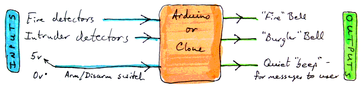
Whenever I say "the system is armed", I mean that it is "watching" for an intruder. (It "watches" for a fire at all times.)
The alarm controller expects three inputs. While the program has been written to make changing the exact details easy, as presented, the three inputs should connect to ground to indicate that there is a fire, that there is an intruder or that you want the system armed at this time. Otherwise, the inputs can float (be connected to nothing), or they can be connected to 5v, if you like... but floating is easier usually. (You do need to include the usual line of code (explained in my page dedicated to the basics of Arduino inputs) if you want to let them float high.) (You can, of course, leave the fire detector input and fire bell output unused. If you do, tie the input high.)
Regarding the input for "I want the system armed": Yes... as far as LokB16 is concerned, that can be driven by a simple toggle switch. That would be a bit easy for a burglars to "defeat"... but only if they know where the switch is, and how your system works.... and why should they? Fancier, more secure arming/ disarming provision is possible without making any changes to LokB16, or you can incorporate, say, a keypad authentication into the code presented here. (Or link the alarm to an RFID tag moderated access system. I just happen to have published a similar article, with the Arduino code for an RFID tag access controller. It has controlled the access to my home and another for a number of years.
But! To get back to the present project....
The "There is an intruder!" input would typically be hooked up to some passive infra-red detectors... PIRs. (Often available on eBay at modest prices... $8?)
The "fire" detector should be connected to a smoke detector... but you'll need to find one with a digital output. If the listing of a device says it has a relay output, that's one that will do for you. (I found one in April 2014 on eBay which looks okay costing $9 including p&p... and a "proper one", in an enclosure, not one of the mere modules, available for less.) Or, if you can find one, one of the old fashioned fusible link devices is better than nothing. (And won't trip the alarm when the toast burns. But have a smoke detector, or even several, and test them. A good stand-alone unit is probably best. Your life is not something to trust to homebrew electronics.)
The programming has been done with an eye to keeping it easy for you to adapt the program to accommodate different bells, buzzers, etc.
Obviously, one output is for the big, loud bell to go on the outside of your house, to call for help when the system sees a burglar.
A second output is for a second bell, this one to "say" that a fire has been detected. It is Very Naughty... but quite easy, in the software, to get one bell to stand for either alarm condition. If you run the two inputs to a little bit of external hardware, it is easy (and not expensive) to have one bell serve both needs, giving, say, a continuous racket if there is an intruder, and a pulsed noise to say "Fire". A few notes in relevant places to tell people which sound is from which cause, for when the bell is going off would be a good idea.
The last output is to drive a little piezo sounder (or LED) which can beep quietly (or wink) at you with messages like "I am about to arm the system" or "If that's you who just tripped one of the detectors while the system was armed, you'd better do the right thing quickly, as the burglar bell is about to go off."
That's the basic story of the basic inputs and outputs. And all you need to understand or build the alarm system described here. In this section, I will discuss some "frills" you might want to consider. None of them require any changes to the software presented here. In a moment, you will be given a way skip over this section, but first...
I made the choice when designing this software to make it capable of turning either (or both!) of the bells on... but not to provide any way "simple" way to turn them off. However, if you reset the system, it always comes up in a "bells off" condition, so I thought, "why bother with anything fancier?" Bells go off: Reset the Arduino. (Or do a power cycle... off, then on again.)
This is robust... You shouldn't have false alarms. But you should never put a loud bell on the outside of a building which will not turn itself off reasonably quickly. It is against the law in many places, for a start.
Between what is described here and your burglar and fire bells, you should incorporate a (professionally made) small bit of hardware, readily available ("timeout module"), which will shut the bell off after, say, 20 minutes, regardless of what your (amateur) alarm controller is saying.
Now you can skip over this section to get to the story of building the system, if you wish!
Other frills I have in my system: Once a bell goes on, a very loud "screamer" goes off inside the house, and a strobe starts flashing on the outside of the house. Both of these are "upstream" of the timeout module, and so will continue operating until the system is reset. The "screamer" is to make things so unpleasant inside the house that a burglar won't indulge in the 5 minutes he can safely ignore the alarm while the police come from wherever they may be. The strobe makes it easy for people in the street to figure out which alarm is ringing, and to alert me (when I return home) to an alarm event if no one notices before the timeout has silenced the bell.
There are two "arm it" switches in the house. The upstairs one is a DPDT switch. When I throw that, I arm the system, but I also bypass the upstairs PIRs. I flip the upstairs arming switch when I go to bed... the alarm is armed, but I can still move around upstairs. In other words, I have selective arming, with "not armed at night" zones... all in hardware. Not difficult to do, and it is much harder for Mr. Murphy to introduce a "bug" into a DPST switch than it is for him to put a bug in even a simple program like the one presented here. (LokB16)
The "arm it" signal already also turns on my CCTV system, and when I can get to it, it will also turn down the thermostat setting, so my house is not kept as warm when I am out, or in bed. (The CCTV switches off when I disarm the alarm.)
The "arm it" signal is also routed to another system in my home which monitors various things and records events. So I have a record of every time the system has been armed or disarmed, complete with a date and time of day... even though the LokB16 hardware has no real-time clock, or data storage. (You could add both to an Arduino based alarm system, of course... but I prefer my "divide and conquer" approach, and I prefer to use a PC when time and data storage are issues. A PC is also worth the downsides if you want, as I do, to display various parameters (indoor/ outdoor temperature, alarm armed/not, etc) in graphs.
There is a room which I don't enter often, but a burglar would be sure to check out. I can go into the room at any time... but even if LokB16 is "dead", leaving the door to that room open for longer than it takes to go in for something, without closing the door as soon as you are through it, will trip the burglar bell. This "alarm system" is also active even if I forget to arm the system when I leave the house. If I need that door open for extended periods, there's a toggle switch (in an out of the way place) which will disable the sensor.
So... those are some of the things you can do with a system with little LokB16 at its heart. Don't let its "simpleness" fool you!
First we will return to the outputs.
The "BurglarBell", "FireBell", and "Beep" outputs drive what LokB16 assumes to be simple devices... when the output is in one state, the device makes a noise. When the output is in the other state, the device doesn't make a noise. If you use the software as presented here, if the signal is high, the device makes a noise. But it is easy to change the software to operate the other way around, should the need someday arise. Always try to build your software that way. The "secret" is to put the code for turning things on or off into subroutines that do little else. Then there's just one place to tinker should the need arise, and all other issues are nicely side-lined elsewhere.
As explained in the "frills" section above, just because LokB16 "controls" a "simple" bell doesn't mean that "the bell" is as simple as LokB16 "thinks" it is. The simple "on/off" output from LokB16 can be an input to something fancier. If it is, you have done in hardware what I recommended a moment ago that you do in software. You are working in modules (I spoke of subroutines, when talking about software modules.) That is as valuable in your hardware work as it is in software work.
The relevant subroutines are called FireBellOn(), BurglarBellOn() and BeepOn(). They all take a parameter of type boolean, in other words, the parameter will be "true" or "false".
Call FireBellOn(true), and the bell should start making a noise until further notice... regardless of the electrical circuits involved. (Likewise BurglarBellOn.)
Call FireBellOn(false), and the fire bell should go silent. Note that the name is still "FireBellOn", even though FireBellOn(false) is how we turn the bell off. (Likewise BurglarBellOn.)
The BeepOn() routine works the same way.
-----
The following genuinely was my plan for this project, completed before the first line of code was written. One little "thing" had to be added at the end, but other than that, the final product actually matched the original plan. I didn't have to edit the plan to accommodate revisions which emerged as necessary... after I'd started writing code.
Your plan always should be finished before the coding begins. When you achieve that, working on the project is always so much less stressful. I don't always achieve "design plan first/ code solution afterwards" as often as I would like... but that's mostly down to a weakness in my character. I'd much rather "get started" than take the time and the trouble to properly plan where I am going, to think sufficiently carefully about the details. ("Be sure brain is engaged before activating feet.")
That doesn't mean that every detail needs to be pinned down before you start... but you need to know that you will be able to deal with the "details" you have left vague. (The usual trap for the hasty is underestimation of the complexity or consequences of a "detail".) Let me make an analogy with a house remodeling project: You may well postpone deciding what color you will paint a given wall. But if some walls will be tiled, and others painted, you ought to decide which are which before the building starts.
Here is the plan upon which I built LokB16...
Years ago, "structured programming" was popular... and rightly so. It is hard to use its precepts in a multi-tasking, event driven environment like Linux or Windows... but for the Arduino, structured programming is close to being "the magic bullet".
A key element of the "structure" in the name is the concentric blocks you see, mostly in cyan, in the diagram above. Notice that every block is entirely contained within "higher" blocks. You aren't allowed to have blocks which aren't like that.
Get a cup of coffee... you need to take a deep breath before proceeding....
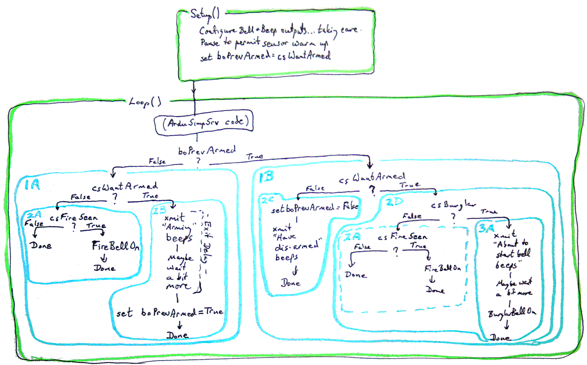
What is LokB16 made of? You would be entirely correct.. if a little unhelpful... if you said "It is two blocks.... a setup() block, which happens once, and a loop() block which happens again and again forever.
If you squint a bit, looking at the diagram above, you will see that this is all that LokB16 is. The green outlines delimit the two blocks.
We'll look at the details of setup() later, maybe.
If your questioner wanted to know more, you could say...
"The Loop() block works as follows...
"Each time though loop(), first you do some code relating to ArduSimpSrv, then you ask if the variable boPrevArmed holds "true" or "false", and do block 1B when it is true, and block 1A when it is not."
Whoa! Lots to discuss arising out of all of that.
a) You don't have to think about the ArduSimpSrv code at this point. For not, "doing" that block doesn't entail doing anything.
b) The block names are pretty abysmal. Try to use more meaningful names for things.
c) I made a mistake in the layout of the diagram... but at least I was consistent. I should have put what you do when something is TRUE at the left at each "if" fork. Then then code and the diagram would "match up" more intuitively.
d) What's this "boPrevArmed" variable? Simple! It keeps track, as the program executes, of whether the system was armed the last time we went around the loop()) code. The first time we go through the loop() code, boPrevArmed already has a value in it, depending on the state of the "Arm it" signal as we passed through setup().
The successful design of "flag" variables such as boPrevArmed is one of the essential skills of the master programming artist.
As we go through loop(), often the system will either stay armed or stay not-armed. If the state of the system changes, the contents of boPrevArmed needs to be changed... quite late in the day... so that the next time we go through the code in loop(), the right message is waiting in the flag variable.
So! Blocks 1A and 1B: We do one (1B) if the system was previously armed, and the other if previously it was not armed.
In both blocks we check to see if there is a fire yet, and deal with it if there is.
We enter Block 1A if the system wasn't, previously, armed. So we look to see if someone has changed the "I want the system armed" switch to "Please arm it"... and then deal with that, if the switch has been changed.
We enter Block 1B if the system was, previously, armed. Now we are watching for burglars and looking to see if someone has changed the "I want the system armed" switch to "Please dis-arm it"... and then deal with either of those, should they arise.
Notice how, at each stage of this, we are able to state "everything" that is happening... at least at some level? Learning to describe a requirement in general terms first, and then break down the parts, and break them down, and break them down until you get to sub-modules with all the necessary details for a programmer to write the code to do "that", is another of the great arts that you learn by doing, once you get the idea of what you need to do.
So far, we have....
"The program consists of...
Get the idea?
I'm not going to do a "blow by blow" of the sub-modules and sub-sub-modules.... but I will make a few selected comments...
At the bottom of each innermost module, I've put "done". This isn't really necessary, if you understand the way the diagram should be interpreted, but it isn't a bad idea to put in those "done"s, as it is a way to explicitly mark the potential paths which you have fully dealt with, as distinct from the paths which still need to have all of their "bits" written out.
See the block 2A inside block 1B? Notice the dotted line around it. That line was drawn dotted to remind me that what is supposed to happen in block 2A has already been described. We are going to use one bit of code twice! (Which has numerous benefits!)
"Xmit" is short for "transmit". Where you see, for instance, "Xmit arming beeps", I mean that you send a series of beeps out on the beeper in a "code" which users will have been told means that the system is being armed.
In Block 2B: The section marked "Exit delay": When you arm the system, it will not matter if one of the intruder detectors "sees" you until the code for Xmit Arming Beeps and Maybe Wait A Bit More has executed. (This can be helpful if your ArmTheSystem switch is in a part of the house "watched" by one of the PIRs. Sadly, due to one "flaw"(?) in the design, although you will be able to arm the system in such circumstances, you will not be able to successfully dis-arm it, unless you can operate the switch before one of the PIRs has seen you.... unless you want the hassle of doing a system reset during the "I'm about to ring the burglar bell" grace period.
So! There's the plan. As I said, I genuinely finished all of that, as you see it, before I started coding. (Of course, this is not my first burglar alarm program, and way not my first program!) But it is still something to aspire to.
There is one little flaw in the design.
I'd rather there were none, and what I am about to say may sound like an excuse... but it is more than that.
Even though the plan wasn't perfect, because the program was planned, making alterations was quite simple.
The flaw is this:
Once one of the bells starts ringing, it should... and will... keep ringing. However, if it is already ringing, but whatever started it, say a fire being detected, is still true, we don't want to be told again that the system is "going to" start the bell ringing!!
The code to "fix" that little problem amounted to just six lines. Each is marked "//... patch of 15Oct11" in the full sourcecode for the alarm system.
With the plan done, coding is quite straightforward. I started with the following initial skeleton....
Initial skeleton...
//LOKB16

//Inputs...
int8_t bArmedWantedPin=3;//
int8_t bBurgSeenPin=4;//
int8_t bFireSeenPin=5;//

//Outputs...
int8_t bBeepPin=12;//
int8_t bBurglarBellPin=11;//
int8_t bFireBellPin=10;//

//"int8_t" is 8bit, unsigned

boolean boPrevArmed;

//****************************
boolean csWantArmed(){
return true;
}

//****************************
boolean csFireSeen(){
return true;
}

//****************************
boolean csBurglar(){
return true;
}

//****************************
void ArduSimpSrv(){
}

//****************************
void setup(){

}

//****************************
void loop(){


}
It won't, of course, DO much... but it does actually compile! (Use Sketch | Verify/Compile, or Crtl-R.. don't try to upload.
It has many of the main building blocks.
We did our designing from the "top" "down". We will do our code development from the "bottom" "up".....
Start by making sure the inputs and outputs work. To do this, we need to...
1) Wire up the hardware... or stand-ins for the various devices...
2) Write the (final) config lines in setup()
3) Write the (final) code for many functions... i.e. the BurglarBellOn, FireBellOn, BeepOn and various cs functions, e.g. csFireSeen. (The "cs" is for "check signal"... i.e. the function checks the signal from a sensor.)
4) Write a little bit of code to go in loop() which, for the sake of tests, ring the Bell when csBurglar true, and turns the Beeper on when csFireSeen returns true. (Each "if" statement implied by that will also have an "else" part which turns Bell and Beeper off if Burglar nor Fire seen. The two channels will be independent...
i.e...
void loop(){
  if (csBurglar()) BurglarBellOn(true); else BurglarBellOn(false);
  if (csFireSeen()) FireBellOn(true); else FireBellOn(false);
  if (csWantArmed()) BeepOn(true); else BeepOn(false);
  }
Note that depending on the way they are wired, the signal coming from different sensors may be "inverted". In other words, let's say that the signal on the "FireSeen" input is HIGH when there IS a fire seen. That doesn't mean that the signal on the "Burglar" signal will also be HIGH when there's a detected burglar. That sensor circuit may work "the other way around", and give you a LOW voltage when a burglar is seen. Happily, because of how the software is written, accommodating such things is easy... you merely change one or more "HIGHs" to a "LOWs" (or vice versa) in the code below!
Until your system executes that code properly, turning BurglarBell, FireBell and Beeper on and off at the right times, you have things to fix! Either in the subroutines, or in the wiring. Get them fixed now, while things are simple. That's the secret of what we are doing: At any given stage, there are as few things to go wrong as possible! And we can test that at least some elements of our project are working... or revise them until they are!
Does that scrap of code seem laughably simple to you? Fine! Go off and do something less simple. You be the hare. I'll be the tortoise. See you at the finish line.
If you keep it simple, you will probably be able to see what you are doing, and are less likely to do something wrong.
The only trouble? Keeping it simple isn't simple. It is one of the fundamental arts of programming, and developing it takes years. Wisdom is what you get from Experience. Experience is what you get until you have Wisdom.
At this stage, you may well have LEDs standing in for the bells and the beeper, and simple toggle switches for the "armed" input. And momentary or toggle switches on the Burglar and FireSeen inputs. No problem... but try to mimic what the real circuits will do in due course, i.e. does the detection of a burglar open a circuit, or close it?
So.. you have a system which....
At this point, you may realize that we're "nearly done". All the pieces are in place. It may seem that after this it is just a matter of setting and clearing things in the right places, and you're done! That's true. Sadly, getting those "few details" sorted out can may be harder than you may be hoping! Happily for you, in this case, the answer is below.
But take a moment to think about our design process. We MADE A PLAN before we started. We worked hard then, to avoid having to work very hard later. Always easiest to build something right in the first place than to build it "nearly right", and then have to go back, find the flaws, apply fixes.
That isn't to say that we always "finish" a project in one leap. The project may start with modest objectives, and when that much is working, additional functions can be bolted on... especially if the want to do that was considered while the "first stage" solution was being designed.
Having started with our overall wants, and then done an overall plan, next we start building the device, And the building starts with basic components, and makes sure they are working before the good engineer tries to use those components together to get the final result.
So far....
//LOKB16

//Inputs...
int8_t bArmedWantedPin=3;//
int8_t bBurgSeenPin=4;//
int8_t bFireSeenPin=5;//

//Outputs...
int8_t bBeepPin=12;//
int8_t bBurglarBellPin=11;//
int8_t bFireBellPin=10;//

boolean boPrevArmed;

//****************************
boolean csWantArmed(){
if (digitalRead(bArmedWantedPin)==HIGH)
            return true; else return false;
}

//****************************
boolean csFireSeen(){
if (digitalRead(bFireSeenPin)==HIGH)
            return true; else return false;
}

//****************************
boolean csBurglar(){
if (digitalRead(bBurgSeenPin)==HIGH)
            return true; else return false;
}

//****************************
void BellOn(boolean boOn){
if (boOn) {digitalWrite(bBellPin,HIGH);}
      else{digitalWrite(bBellPin,LOW);}
}

//****************************
void BeepOn(boolean boOn){
if (boOn) {digitalWrite(bBeepPin,HIGH);}
      else{digitalWrite(bBeepPin,LOW);};
}

//****************************
void ArduSimpSrv(){
}

//****************************
void setup(){
/*Configure inputs... No pinMode stmt needed... Arduino pins
   default to "set for input"...
   but we may want to "connect" the internal pull up
   resistors, depending on how you wired the sensors
   to the Arduino.*/
//digitalWrite(bArmedWantedPin,HIGH);
//digitalWrite(bBurgSeenPin,HIGH);
//digitalWrite(bFireSeenPin,HIGH);

//Configure outputs...
pinMode(bBeepPin,OUTPUT);
pinMode(bBellPin,OUTPUT);
pinMode(bFireBellPin,OUTPUT);
}

//****************************
void loop(){
  if (csBurglar()) BurglarBellOn(true); else BurglarBellOn(false);
  if (csFireSeen() FireBellOn(true); else FireBellOn(false);
  if (csWantArmed()) BeepOn(true); else BeepOn(false);
  }
When the "little details" (mentioned just before the code above) are taken care of, we are left with the finished code for LokB16- Arduino Fire and Burglar Alarm. (The link takes you to an ordinary web page, with the code. You just use copy and paste to import it into your Arduino development environment if you want to use it.)
Have a read though the sourcecode because there is more "tutorial" material in the remarks embedded in the code. Make good use of such embedded documentation in your own work. Part of the joy of writing these tutorials for you is that it forces me to do PROPER inline documentation within things that I am writing for my own use, but getting a tutorial out of as a bonus.
It is not "important", but you may be amused by the code put into LokB16 to allow programmers to send "Morse code" easily. (When the system is about to start the BurglarBell ringing, it sends "SOS" a few times to announce that the racket is imminent.)
As I've said before, further up the page, the sourcecode for my 'LokB16' Burglar Alarm controller is hosted on its own page. You just copy and paste from that page to your Arduino compiler/ uploader.
I hope that was useful? Let me know if there are areas which weren't adequately explained? Let me know what "Gotchas" got you?
![]() Page tested for compliance with INDUSTRY (not MS-only) standards, using the free, publicly accessible validator at validator.w3.org. Mostly passes. There were two "unknown attributes" in Google+ button code, and two further "wrong" things in the Google Translate codeSigh.
Page tested for compliance with INDUSTRY (not MS-only) standards, using the free, publicly accessible validator at validator.w3.org. Mostly passes. There were two "unknown attributes" in Google+ button code, and two further "wrong" things in the Google Translate codeSigh.
CSS behind the page checked, at least once upon a time!, with http://jigsaw.w3.org/css-validator/
Why does this page cause a script to run? Because of the Google panels, and the code for the search button. Also, I have some of my pages' traffic monitored for me by eXTReMe tracker. They offer a free tracker. If you want to try one, check out their site. Why do I mention the script? Be sure you know all you need to about spyware.
....... P a g e . . . E n d s .....