Tags in the form of buttons ($4) (thin, 1.6cm across, no holes) or credit cards ($2) or keyring fobs are available too.
This page is browser friendly, by the way. Make your browser's window less wide than your whole screen and you will find the narrower columns much easier to read.
The page is in two parts...
a) At the top, there's a very basic program, introducing you to using the RFID reader with an Arduino.
b) At the bottom is a second version of the program. It has been created by slightly modifying the first, to create something to open a door when either of two specific RFID devices are brought near the reader.
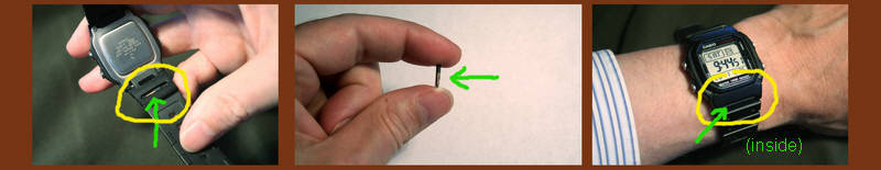
Before we get down to work, how's this for a neat way to carry an RFID tag with you everyday? The central photo shows the tag. It is a small glass capsule. Sparkfun sell them in this form for about $5. My watch strap just happens to have a little cavity, just the perfect size, on its underside. I'm still looking for the "perfect" glue to hold it in place. Hot-melt glue wasn't the answer.
Be advised: Tags come in several "flavors". Be sure when ordering tags for your reader that you order the right sort. (Each of the "right sorts" is usually available in multiple forms, e.g. key fob, class capsule.)
Tags in the form of buttons ($4) (thin, 1.6cm across, no holes) or credit cards ($2) or keyring fobs are available too.
In this page I will show you the basics of connecting an Innovations ID-20 RFID reader, available from Sparkfun.com, to an Arduino. ($35, (+p&p, 12/11.. unchanged at 2/19) While the essay was written while working with an ID-20, I don't believe that users of the ID-12 would do anything different. (The ID-12 is less expensive, $30, (+p&p, 12/11 & 2/19) but doesn't read over such a long range (120mm spec, vs 180mm)... In hindsight, I don't thing the extra range of the ID-20 makes any difference to me, in my application. I have the ID-20 behind a pane of glass, and "wipe" my RFID tag across the glass. I don't think the ID-12 would have trouble. But $5 to the extra power doesn't seem much either.
I have to bring my tag within about 8cm of the reader anyway, so being closer isn't a problem. See below for an even less expensive option.)
If you take my advice, if you buy the Sparkfun product, you will also buy two of the 2mm socket strips that Sparkfun stock for you. Sadly, the useful breakout board Sparkfun used to offer was listed as "retired" 2/19. But it's no big deal. (It was Part SEN-08423, 95 cents, if you want to look at the spec. (Search on SEN-08423, then follow the obscure "retired products" link at the bottom of the results page. Let me know, if they bring it back into stock, please? Sorry- the pin numbers used below are the pins as numbered on that, but figuring out what you need to shouldn't be hard.
After I'd built one instance of my RFID access control solution, I encountered a different source for a reader... $11 (+p&p, Dec 11)... to go at the heart of it, ITeadStudio.com. Alas, they no longer do one, but there are many sources. (Be sure the one you are considering offers serial output, though.)
The software presented here works fine with either reader, without tweaks. I've bought 125mHz tags from Sparkfun, from ITeadStudio, and from an eBay source... all work fine with either reader. ITeadStudio has some nice 28mm "key fob" tags, and they don't emblazon their logo across their product.
Speaking of eBay... in addition to the tags I did receive... I saw some tags on eBay at a "too good to be true" price... and it was. Despite sending $3.98 by PayPal (Aug 11) to xiao2huan for something very like item 150632480332 (Dec 11), and a civil exchange of emails, no tags ever arrived, not the first shipment, not promised replacement. Have you ever tried to "work with" eBay when there's a problem? For a start, I can no longer call up the item description to see how the seller was listed. (Seller names and PayPal accounts are often different, sometimes for good reasons.) There is a price for everything. I often get good deals via eBay... but it is not unknown to be out of pocket. I look at it as just the price I pay for the good times.
Enough about the reader! I should also mention the "Arduino" I've had the code in for at least 8 years of trouble free access to my home. I built this project with a Modern Device RBBB. $6, kit form (very easy assembly. Available assembled. (Usually $11)) 2/19 sale.
These are the only connections you need to make....
That's about it! In the data sheet you will read that pin 10 is an output which, properly connected (at least a resistor... probably transistor plus resistor) can drive an LED, which will light when the reader "sees" an RFID device. Not necessary to what follows, but I mention it, just in case your needs are different.
At this point, you can continue reading, and cover some background information which I think you might welcome, or you can "skip to the end", to go straight to the RFID-controlled door lock material.
Here are the essentials from that, in diagram form...
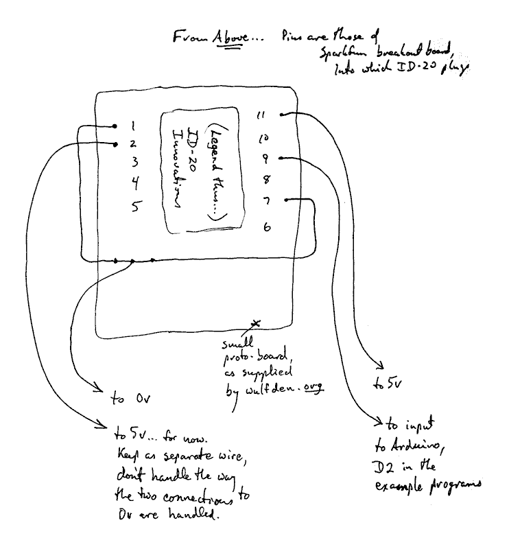
The arrangements for pins 1 and 7 are done that way to accommodate the particular proto-board I use, which has only a single connecting point outside the footprint of the Sparkfun breakout board.
While with the simple software I am using at the moment, there is no need to be able to change the state of pin 2, and it should be kept at 5v, that pin is an input to the reader, and by having two long wires, one from pin 2, one from pin 11, to your source of 5v, you will be able to use the pin 2 input later, if you decide you want to use the feature it controls.
Pin 9 from the RFID reader is where the reader outputs (TTL, inverted) what it reads from RFID devices... when the reader is configured for its ASCII mode, which it will be, if you've connected it as above.
Leave the other pins connected to nothing. Don't worry about floating inputs.
You will have to check the datasheet if you have an ID-2. They are similar devices... but there may be some minor but significant differences to accommodate. I don't believe that anything I've said here about working with the ID-20 doesn't apply equally to working with the slightly less expensive, slightly less sensitive ID-12.
Put the following into your Arduino, switch over to the serial monitor, bring an RFID device (of the proper type) near the reader, and you should see something like.....
2 48 48 51 54 53 70 56 65 50 55 67 52 13 10 3
Move the RFID device away, bring it back again, and the line should be repeated. Move the RFID device away, bring a new one near, and a different (but similar) line should appear, perhaps...
2 52 50 48 48 52 52 55 55 51 53 52 52 13 10 3
The strings always begin with a 2 and end with a 3. You can add code to check that these are seen, as a check that the unit wasn't outputting rubbish, or that you misread what it sent.
It is possible to bring the RFID device back again too quickly after moving it away. If you think your reader is "missing" presented devices, be just a little deliberate in your "move it away"/ "move it back" process. The reader stops reading after it reads a device once until it detects no device present. It then "re-arms" itself. Having said all of that, it should be able to do, say, three reads in five seconds.
The next 10 bytes will be the ASCII for the RFID device's unique code.
The next two are a checksum, which you can ignore for now, or treat as part of the unique code from the RFID device. (The code presented here doesn't actually do anything except tell you the number carried by the RFID device. When we extend it to make an electronic lock which opens when the first device above was brought near the reader, we will add code which deals with what the following pseudocode implies:
if (device seen had
   48 48 51 54 53 70 56 65 50 55 67
      in it) (then) OpenDoor
As the RFID device with that code is one that I own, the lock wouldn't be much use to you... you would have to change the number to the number inside an RFID device you own!
Going back to our analysis of what the RFID reader outputs when a device has been read...
After the "stuff" already described: Always a 13 and a 10, the codes for "CR" (carriage return) and "LF" (line feed).
And lastly: the number "3", as already mentioned.
The code to make that happen....
//RFIDsimple1
//ver 20 Feb 11, tweaked in webpage, 27 Jun 2011
//started 20 Feb 11

//For http://sheepdogguides.com/arduino/art3rfid1.htm

//Much of this derives from serial interfacing advice at
//  http://sheepdogguides.com/arduino/art4SeSimpFrmIDE.htm
//and
//  http://sheepdogguides.com/dt4t.htm

#include <NewSoftSerial.h>
//Yes, NEWSoftSerial... I don't think SoftwareSerial has the
//critical "available()" function, does it?

const int SerInToArdu=2; //Defines pin data passes
    //to Arduino over from RFID reader
const int SerOutFrmArdu=3; //Not used, but
    //"fills" a parameter in the set up of
    //mySerialPort

NewSoftSerial mySerialPort(SerInToArdu,SerOutFrmArdu);
//  Creates serial port for RFID reader to be attached to.
//  Using pins 0 and 1 is problematic, as they are also
//     connecting the development PC to the Arduino for
//     programming, and for the output sent to the serial
//     monitor.

void setup()
{
Serial.begin(9600);//For access to serial monitor channel
Serial.println("Bring an RFID tag near the reader...");
mySerialPort.begin(9600);

};

void loop()
{
int incomingByte=0;//create and initialize a local variable

//The "then" part of the following will only execute
//  after the RFID reader has sent something to the Arduino
if (mySerialPort.available() > 0) {
		// read the incoming byte from the serial buffer
		incomingByte = mySerialPort.read();
		// show what was received
		Serial.print(incomingByte, DEC);
                Serial.print(' ');
                if (incomingByte==3) Serial.println();
     };
}
That's the heart of reading RFID tags with the Innovations modules from Sparkfun and others! Not too hard to follow, I hope? If you need help with the concepts associated with reading a stream of serial data from something outside the Arduino, my tutorial about how to send information to your Arduino from a PCmight be useful... but that might merely distract at this point. The above should Just Work.
The simple demo above can be extended to make an access controller based on the Sparkfun ID-20, which interfaces easily to the Arduino easily.
You'll need some way to unlock whatever you are controlling access to. An electromechanical strikeplate may well be part of the answer.
On the software front, the program above is fine for determining the number supplied by a given RFID tag, and it is a start on a program that, for instance, opens a door when a particular tag is presented.
First let's look at how we deal with the fact that your program and the reader operate "asynchronously". At the moment that the reader picks up the presence of a tag, and sends the number to your program, your program may be "away", doing other things.
Happily, the Arduino employs buffers, and the NewSoftSerial library has an "available()" function. Also, every string from the reader begins with a "2", and ends with a "3". They allow you to confirm that you are reading one string of bytes from the reader, not the second half of one, and the first half of a subsequent string.
(You can skip over this section, if you are in a hurry, and don't care about some minor details.)
If you provide your system with an LED to flash with a message, you can get it to report to you when it reads something that can't be right.
What do I mean by that?
In the simplest case, I would merely check the 12 bytes between the "2" and the "13 10 3", and if they matched what one of the authorizing RFID tags would present, I'd open the door.
The fancier program would add a check to see if the program is seeing possible numbers. How, in the simple case, do we detect a misread?
How, in principle, do we detect a misread in a fancy case? Like this...
The first ten bytes returned after the "2" are, strictly speaking, the number embedded in the tag. The next two bytes, if all is working properly, will always be the same for a given preceding ten bytes... but WHAT those numbers should be follows a rule. They are a "checksum". (The link will take you to the Wikipedia article, which you don't need to read.)
Forget the RFID reader, etc, for a moment. I'll give you a very simple example of a checksum.
Suppose that you had to build something which would merely send a single digit from "A" to "B" every thirty seconds, but it won't always be the SAME digit. And further suppose that you are concerned that because of the way you are sending it, the data may become garbled... it might happen that a "5" sent from "A" might be received as, say, "7" at "B".
A very simple checksum could be done as follows.
Every thirty seconds you would, as before, send a digit. But then, in addition, you would also send a second digit, a checksum. If you sent a 1, the checksum digit would be a 9. If you sent an 8, you'd send 2 as the checksum. Etc...
Data  Checksum
 1      9
 2      8
 3      7
 4      6
 5      5
 6      4
 7      3
 8      2
 9      1
At the receiving end, you compare the digit received and the checksum received, and if they don't add up to 10, you know that one or the other became corrupted in transmission.
The RFID tags read by the Innovations readers do something which is virtually the same, just a bit more "clever"....
We have to take a little digression into number systems.
In the program at the top of the page, the data from the RFID tag is read and displayed as, for instance,....
2 48 48 51 54 53 70 56 65 50 55 67 52 13 10 3
Discard the "wrappings"... the "2" at the start, the "10 13 3" at the end.
Now go through and "translate", using the ASCII code. That turns what we had above into....
48 48 51 54 53 70 56 65 50 55 67 52
 0  0  3  6  5  F  8  A  2  7  C  4
(You can use an online ASCII code table, but all you really need to know for this is....
Decimal Stands for
  48       0
  49       1
  50       2
  51       3
  52       4....
and
  65       A
  66       B
  67       C....
Take the translated bytes, and write them out in pairs....
00
36
5F
8A
27
C4
If you treat these as hex numbers, and XOR the first 5, the result should match the last number, &C7. (The "&" prefix tells you that I mean a hex number by the "C7".)
Hmmm... I apologize to those of you who by now have a headache. On the other hand, many readers won't have a headache... it isn't as hard as it may seem if you haven't met this sort of thing before. I will try to present some code for you one day. If any other Arduino user would like to send me a subroutine to return a boolean to tell us if the first 10 bytes and the 2 checksum bytes cross-check, I'd be grateful... not least for your ideas of the simplest, most beginner- friendly- without- being- too- inefficient way of holding the data from the reader! (If you would like your website promoted when I incorporate your work here, don't hesitate to send me the URL to include.)
I hope the above answered some questions for you? Don't hesitate to write and tell me what your main remaining questions are... or use the excellent Arduino forum to get answers... they are probably already in the forum archives, if you don't want to wait for your question to be re-answered....
I now have my front door opening when I present an RFID tag to a reader in a window by my front door. The RFID tag "lives" in a crevice in the strap of my wristwatch.
First the code. It is derives from the program above, with (really!) just a little added. There are comments in the code to help you follow what is going on.
//RFIDcrude1
//ver 22b Feb 11
//Derived from RFIDsimple1
//started 22 mar 11

//For http://sheepdogguides.com/arduino/art3rfid1.htm

//Much of this derives from serial interfacing advice at
//  http://sheepdogguides.com/arduino/art4SeSimpFrmIDE.htm
//and
//  http://sheepdogguides.com/dt4t.htm

#include <NewSoftSerial.h>
//Yes, NEWSoftSerial... I don't think SoftwareSerial has the
//critical "available()" function, does it?

const int LockPin=4;//pin to control electromechanical
//    strikeplate (EMS) and optional LED.
//EMS: http://www.arunet.co.uk/tkboyd/ec/ec1ems.htm
//Change pin used  if you wish.
//DO NOT USE PIN 13 FOR THIS.
//Consider your lock-driving circuits carefully...
//   is LockPin high, or LockPin low the best state
//   to use for "open door"? You don't want the
//   door opening in various possible fault-states,
//   do you?
//I think (not well tested) that you only need to change
//   the next line to invert the logic of the locking
const byte Locked=LOW;
const byte Unlocked=!Locked; //"not" locked... i.e. Unlocked will
//   be made LOW, if Locked=HIGH

char sFrmTag[13] = "123456789abc"; //Yes... 13 if you
//   need to store 12 characters. Initial contents
//   arbitrary. A place to accumulate string returned
//   from reader.

byte bTmp;

const int SerInToArdu=2; //Defines pin data passes
    //to Arduino over from RFID reader
const int SerOutFrmArdu=3; //Not used, but
    //"fills" a parameter in the set up of
    //mySerialPort

NewSoftSerial mySerialPort(SerInToArdu,SerOutFrmArdu);
//  Creates serial port for RFID reader to be attached to.
//  Using pins 0 and 1 is problematic, as they are also
//     connecting the development PC to the Arduino for
//     programming, and for the output sent to the serial
//     monitor.

boolean TagMatch(char sToMatch[13])
//This subroutine uses Bad Programming by
//   referring to a global variable
//   within itself (sFrmTag)
//
//For some reason, I couldn't get...
//   "if (sFrmTag=="8627A6B73544")..."
//   to work.
{ boolean boTmp=true;
  for (byte bTmp=1; bTmp < 13; bTmp++)
    {if (sFrmTag[bTmp]!=sToMatch[bTmp])
       {boTmp=false;};
    }
  return boTmp;
};//end of TagMatch

void OpenDoor()
{
Serial.println("Opening door");
digitalWrite(LockPin,Unlocked);
delay(3000);
Serial.println("Re-locking door");
digitalWrite(LockPin,Locked);

};

void setup()
{
mySerialPort.begin(9600);
pinMode(LockPin,OUTPUT);
digitalWrite(LockPin,Locked);
Serial.begin(9600);//For access to serial monitor channel
Serial.println();
Serial.println("Bring an RFID tag near the reader...");
};

void loop()
{
int incomingByte;

//The "then" part of the following will only execute
//  after the RFID reader has sent something to the Arduino
if (mySerialPort.available() > 0) {
		// read the incoming byte from the serial buffer
		incomingByte = mySerialPort.read();
		if (incomingByte==2){bTmp=0;}//no ; here
                  else {
                       if (bTmp<12) {
                                     sFrmTag[bTmp]=incomingByte;
                                     bTmp++;};
                       }
		Serial.print(incomingByte, DEC);
                Serial.print(' ');
                //The "Serial.println"s in the following only for
                //debugging, and as a way to find out the key
                //in a new tag. If the tag is misread, you will
                //sometimes get weird results... it would be best
                //to test that incomingByte is 0-9 or A-B before
                //appending it to sFrmTag[], above.
                if (incomingByte==3) {
                                      Serial.println();
                                      Serial.println(sFrmTag);
                                      //Following hardcodes the program
                                      //to open the door for either of
                                      //two tags I have...
                                      //You'll have to change the values
                                      //sFrmTag needs to match.
                                      //Note that I have included the
                                      //checksum as part of the tag's
                                      //"number"
                                      if (TagMatch("8627A6B73544")||
                                          TagMatch("0038CA584684"))
                                           {OpenDoor();}
                                      };
     };//end of loop()
}
.... and here is the circuit I used, "downstream" of the Arduino...
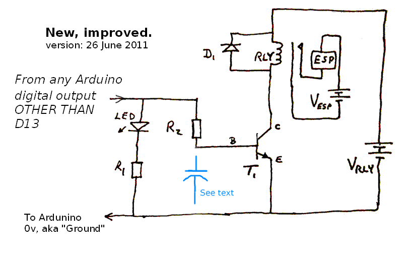
It isn't "perfect", but it was the quickest path to something that works, given the power supplies, etc, I had on hand. Actually, it is probably pretty good, if you substitute a "better" resistor than the BC549 I used... but a BC549 will work! (If any experts could send in advice I could post here about what to look for when trying to get the "right" transistor, I'd be grateful. Email address at bottom. Help for the newbie choosing a transistor would be even better than just the part number of one or two suitable devices. By the way... while asking you, experts, for help... Is my conclusion that the higher-than-5v coming from Vrly cannot, for some reason, "push" its way "up" through the base of the transistor to do Bad Things to the Arduino output? If you could explain all of that in more scientific terms, I'd be interested.)
R1: 300 ohms. R2: 2K2. T1: BC549 (Probably not idea. What I had!)
Working left to right across the diagram...
LED is just to give you a visual indication of what should be happening.
The transistor which came to hand for me was a BC549, an NPN transistor. (I'm no expert on transistors as switches.... but this one works... here... with my other components!)(Want to know more? Try the Electronics-Tutorials guide to transistors as switches.)
"RLY" is a small relay; D1 is The Important Diode you should always have on coils and DC motors (because they incorporate coils). There's more on why you need a "snubber diode" in a separate essay I wrote for you.
"VRLY doesn't have to be a battery, of course. And you might be able to tap it to supply the VUNREG for your Arduino, but I've had bad experiences in the past with mixing the power supply to a relay with the power supply to a microcontroller... and in any case, my relay needed a slightly high voltage
"ESP" is the electromechanical strikeplate which unlocks the door when that is called for. Note how its circuit is completely separate from everything else, thanks to the isolation the relay provides. The electromechanical strikeplate has a big electromagnet, hence coil, hence collapsing fields... and so I like having the circuit separate. (A reverse biased diode should be put across the electromechanical strikeplate, just like the one across the relay's coil.)
Now... about that capacitor...
I had a problem. By a bit of bad luck, I happened to put "unlock door" signal on D13. The positive thinkers among you out there will call it good luck, because I learned something: When the Arduino powers up, and after a reset, before your code executes, D13 is configured as an output, and briefly pulsed high before coming to rest as a low. (The other digital I/O lines will be configured as inputs while the Arduino is powering up... a much more satisfactory default behavior.)
As a result, every time the Arduino was reset, or there was one of the rare but not unheard of power cuts to my home, when the power came back, my front door unlocked.
Don't use D13 to drive the electromechanical strikeplate that locks your door.
If you don't want a "fascinating" excursion, you may skip down to information on PCBs for the Arduino/RFID Access Controller.
Before I became aware of the fact that this brief high pulse on D13 is a "feature" of just D13, I set about "solving" the problem by putting a 1000 uF capacitor in the circuit where shown in blue above.
The capacitor will normally be discharged. When the line from the Arduino goes high, the capacitor will start charging. It will take a little time (in human terms... a long time in electronic terms) for the voltage at the base of the transistor to rise high enough for the transistor to "turn on", i.e. allow enough current to flow to make the coil of the relay change over the contacts in the relay.
This is a Good Thing... because the brief "high" pulse from the Arduino's reset won't be long enough to charge the capacitor sufficiently, and the lock won't be opened in response to the brief pulse. But...
This is a Bad Thing... because it will leave the transistor dissipating large amounts of power for too long. My circuit, with the capacitor, worked fine for many weeks. But during a time when I was converting everything from proto-board to PCB, and activating the lock repeatedly, with little "rest" between activations, I burned out the transistor. It was a bad design, and finally "fell over". This is discussed in detail in the helpful discussion on the subject at the Arduino forum. Note how a specific question, with as many details as possible, even details the poster thinks irrelevant, can bring a rapid, helpful response.
Happily, as is often the case, there was a way to get to where I wanted to be, once I stopped asking the wrong question. Once I stopped trying to make the capacitor idea work, and found out that D13's behavior is idiosyncratic, I was able to "go around" my "problem". (I think that moving the capacitor to the other side of the transistor might work... although it might make the relay "chatter" while the voltage was passing through the level at which the coil pulls in the contacts.... But happily, I don't need to explore all of that now, do I. But I do wonder if... (^_^)... )
You may or may not want the following. You don't need it. It is the PCB I use with my ModernDevice RBBB Arduino clone... but I'm afraid I'll have to leave you to figure out the off-board connections you'll need. Not "rocket science", but don't feel foolish if you are new to this sort of thing and can't make sense of it. It isn't well done for the use of others, sorry. You don't need to provide sockets for all of the legs of the RBBB... just enough to connect the few signals which need to be connected, including the ground, Vunreg and Vreg lines. Strategically add a few more to provide mechanical stability. The image below shows you what the "traces" side of the single-sided PCB should look like. (The "resistor" and diode (D3) at the lower left are NOT part of what should be on the PCB... they show the electromechanical strikeplate which you are going to drive with the circuit, and an extra snubbing diode.)
If you don't happen to use the RBBB for your Arduino work, fear not... the board would still save you a lot of time.
Connections between my board and Arduino...
I have a wall-wart producing an unregulated (and somewhat variable!) 8v. That goes first to my board (PCB235), to power the relay coil, etc, and from there is passed on to my RBBB. I have a link on PCB235 which allows me to disconnect the V-unreg feed to the RBBB when I am powering it via my USB programming cable.

You may download an Eagle CAD file for that board, too, if you wish. But you will need the Eagle CAD package. There was an impressive free version for hobbyists. The trial was... not fatally restricted, and no time limit. Windows, Linux, Mac. Even in "the old days", if you want to profit from things done with the Eagle CAD, you have to share... There was a "lite" version for only $49 (6/11). March 2019 I discovered that Eagle is now part of the Autodesk portfolio, and I didn't, in a cursory check, see anything about low cost options for hobbyists. See also DesignSpark. I have a separate page about free or low cost PCB design tools. "Free or low cost" does not mean "rubbish"! SCHOOLS SHOULD use KiCad, so pupils can USE at home what htey learn at school! (Rant ends.)
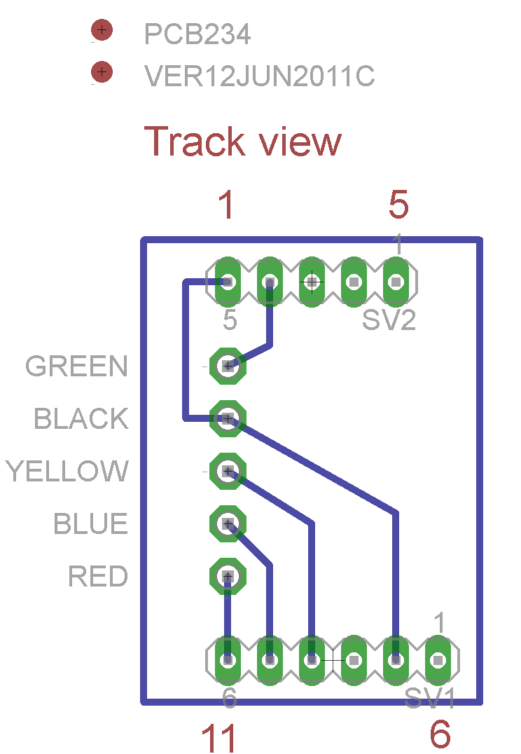
The following will show you how to connect my Arduino-carrying board to the 95 ¢ breakout board Sparkfun offers for the Innovations ID-20 (which they also sell, $35 (6/11)). The breakout board is well worth buying, and buy two of the 2mm pin sockets at the same time, and use them.
You really don't need the following, but it tells you how to connect from my main board (above) to the RFID module. (The "Blue" connection is also called "Green2" in some places. It connects to the ID-20's "B2", which I didn't use in my design, but I thought I might want that signal someday. There is more discussion of these matters near the top of this page.
Nota bene: If you don't use my PCB as a "breakout for the breakout"!, be sure to inter-connect the two pins which need to be carried to the main board via the black wire.
You may download an Eagle CAD file for that board, too, if you wish. If you haven't tried the Eagle CAD package. There was an impressive free version for hobbyists. The trial was... not fatally restricted, and no time limit. Windows, Linux, Mac. Even in "the old days", if you want to profit from things done with the Eagle CAD, you have to share... There was a "lite" version for only $49 (6/11). March 2019 I discovered that Eagle is now part of the Autodesk portfolio, and I didn't, in a cursory check, see anything about low cost options for hobbyists. See also DesignSpark. I have a separate page about free or low cost PCB design tools. "Free or low cost" does not mean "rubbish"! SCHOOLS SHOULD use KiCad, so pupils can USE at home what they learn at school! (Rant ends.)
![]() Page has been tested for compliance with INDUSTRY (not MS-only) standards, using the free, publicly accessible validator at validator.w3.org. Mostly passes.
Page has been tested for compliance with INDUSTRY (not MS-only) standards, using the free, publicly accessible validator at validator.w3.org. Mostly passes.
AND passes...

CSS behind the page checked, at least once upon a time!, with http://jigsaw.w3.org/css-validator/
Why does this page cause a script to run? Because of the Google panels, and the code for the search button. Also, I have some of my pages' traffic monitored for me by eXTReMe tracker. They offer a free tracker. If you want to try one, check out their site. Why do I mention the script? Be sure you know all you need to about spyware.
....... P a g e . . . E n d s .....