I wrote this one hot week in July 2010. I've been leaving my front door ajar, to get some air through the house. Probably not a very good idea. So I thought I'd hook up an Arduino to ensure that no one takes advantage of the door being unlocked.
This essay isn't meant, primarily, to tell you how to make a "fantastically useful" device. While the device is useful, and could be used for several things, the main purpose of this tutorial is the help strengthen your system engineering skills. Even if you don't need (or build) the door monitor, you may benefit from reading the essay. (Latching relays can be made without using a microprocessor!)
For other thoughts on working as if programming is a process of building "state machines", see my long Lazarus tutorial about using the "state machine" idea to convert a BASIC program to Lazarus. Fear not, even if you don't care about Lazarus or BASIC... or the fun "Hunt the Wumpus" game... there is Good Stuff about "state machines"/ "state diagrams" in that.
The door is only open about four inches. It opens inwards, and the top edge is under a portion of wall. I have put magnet on the top of the door and a reed switch on the wall. When the door is open four inches, the magnet causes the reed switch to close. If the door is pushed farther open, the switch opens.
A simple inverter connected to a buzzer would do the job...
... but you'd need an on/ off switch as well, and a clever burglar could quickly push the door back to the four inches position and turn the buzzer off again, maybe before you noticed it(!), etc, etc, and anyway... something that simple wouldn't be any fun, would it!?
So... and here is where the "lesson" in designing gadgets begins... what DO we want?
Always know where you're going, when trying to build systems.
You may sometimes be "going" toward a goal that you "know" you can't attain yet, because you know that there are elements that you can't cope with. But know where you want to go, and with those "big wish" projects, have a reachable intermediate destination in mind before you do much more than dream.
Another "lesson": Think first in broad terms. Then refine your ideas. This is part of what "top down design" means. In my case, sitting nervously at my front desk with an as yet unprotected front door, I said to myself....
I want a way to open the door four inches, arm an alarm, and then know that if the door moves, the alarm will start ringing, and will continue ringing until I do something more than merely putting the door back to where it was.
That statement of where I was going was good. I thought a bit about whether it was actually what I wanted. I thought about whether I thought I could do what would be needed. And then I turned to refining my statement of what my system would do.
Just before we proceed, a quick word about "latching relay". That's what we're making. They come in various forms, but here we will make one that "latches" its output (which controls the buzzer) "on" if a momentary switch is closed. In a latching relay, a second momentary switch has to change state briefly before the output will re-open.
Returning to our plans. We have the top-most layer of our development work done. Now we will work "down" a bit from there.
What will the state of things be just after the Arduino switches on? I'm going to decide that the state will be "Buzzer quiet. System not armed."
By the way: "armed" means that the alarm system is waiting and watching, ready to start making a noise if something unwelcome is seen. In discussions of alarm systems, it is sometimes hard to distinguish between "armed", as defined above, and "tripped", by which I mean that the system has seen something, at a time when it was armed, and the system has started "shouting" "help". If you find anything in the following ambiguous, please write and complain, citing webpage aht1c.htm
The decision I took about the state of the system just after a reset may seem obvious... but things almost always have an overlooked "what if" buried in them. In this case, one such "what if" (which I have chosen not to provide for) is: "What if there is a brief power failure at a time when the door is open, and the system is meant to be guarding against it opening more than four inches?" The system I'm building today is not going to attempt to "remember" whether the alarm was armed or not the last time it was shut down.
Moving on. My requirement was... "I want a way to open the door four inches, arm an alarm..."
I'm going to "arm the alarm" by pressing (and releasing) a button. That may sound "fully planned", but it isn't.
How would I know that the door was open the "right" amount before pressing the button? If it isn't, the alarm will start sounding as soon as I press the button, which would be annoying!
So we refine our plan: The reed switch will not only feed an input into the Arduino, but it will also switch an LED on and off. Now our "I want a way to open the door four inches, arm an alarm..." becomes "... open the door until the LED says it is in the right place, then arm the alarm by pressing and releasing a button."
That sounds so simple, so obvious, when you read an account like this. But unless you go though similar planning of the details of what your system is going to do, you'll find yourself backtracking and reworking things after you have got to the stage of setting up hardware and writing software. It is a lot easier to revise plans than it is to revise hardware or software. The trick is to anticipate and really think through all the little details.
Look again at where we started, and where we've got to. Try to see why the process is called "top down" design. We start with "the whole story" in one sentence. Then we look at details, break them down, break down the broken down bits, etc, until we are really down to good "foundations": simple, clear, complete statements about every one of the details which underlie our overall goal.
We will go down another level with this element of the design, and then go back up and start breaking down another part into it's details.
We've said that users will "press and release a button to arm the alarm". Because the Arduino offers us the convenience of (optional) built in pull-up resistors on the digital lines, we will connect our momentary switch between an input and ground. (I'll say more about this later).
Let's think about the reed switch, and the "door not in position" LED connected with it.
Do we care if the LED is "on" or "off" when the door is in the right position? No? Good... one less design constraint to satisfy. So if we don't care, what's the easiest circuit for the reed switch, LED, and Arduino input? Easy. The one shown above. (I decided I didn't care about which state of the door turned the LED on so that I could use the simple circuit. Had I cared about the state of the LED, I would have had to think harder about the circuit at this stage.)
If the alarm is ringing, we're supposed to be able to turn it off by "something more than merely putting the door back to where it was". I'm going to decide that pressing a button will be that "something". (The program is easily adapted to making the "something" something else. More on that later.) What button? Here's where using an Arduino rather than doing a version of this with simpler components pays off. Can we use the same button as we used for arming the system? Yes. But I thought carefully about that before pressing on. It is inevitable that during the next phase, the bottom up development phase of the project, you will have to reconsider decisions you thought were "made", done with. They should have been done with... but you messed up. It happens. When you have to "go back to the drawing board", be careful that you (try to) think though all of the ramifications of the change to the plans you think you want to introduce. It is bad enough that you have, say, to add an extra switch that you hadn't realized would be needed. You don't want to find yourself taking it (and the software for it) out again in an hour when you discover the next thing you didn't deal with during your design stage. If you have to re-visit the design, look carefully at anything "touching" the bit you want to re- design.
Going back to the system summary, I'm next going to look at "the alarm will start ringing".
Good grief (C.B.), how many angels can you find on the head of that pin??
First a digression: Think in modules. As long as the system has a way to put electricity of the right sort into the necessary wires, it doesn't much matter what sort of buzzer you hook up. In fact, while getting all of this working, I'm not using a buzzer at all. I just have an LED (and current limiting resistor) connected where the buzzer will one day go. Want to use a simple, low power, 5v buzzer? You can probably just plug it in instead of, or even alongside, the LED plus resistor. Want a submarine's "dive, dive, dive" claxon which can be heard from a mile? You'll plug in a relay (with diode, and maybe transistor driver) to the Arduino, and plug the claxon into the other side of the relay. Simple? Well, yes... IF you know your "buzzer" was of the "two wire, give it some DC juice and it sounds" type.
I, however have in mind a little module which runs off of 5v, uses so little power that it can be connected directly to the Arduino. But to "buzz" I need to feed it not simple DC, but a train of ons and offs... but I can get the Arduino to give me such a train of pulses, so that's okay. (More on that later.) But by thinking down to that level of detail, I've saved myself the hassle of a dead end later.
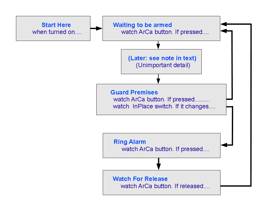
That's beginning to look like a pretty good plan of what the system will do, and what hardware will be involved. Now we're going to do a little more planning, concentrating on the software. The sort of thing below is sometimes called a flow chart, and the one below is also a close relative of a "state diagram". Each box is a "state" the system may be in. And we can see what will make the system leave a given state, and what states it can transition to. I'll confess to the diagram being incomplete. There are too many details about what will go on in the system which are only in my head, not in that diagram... but we'll press on, anyway.
All Arduino programs ("sketches") consist, at the highest level, a "setup" and a "loop" function. At this stage, I'm going to say a bit about how the diagram below will be transformed into an Arduino program.
There's no need to say much about what will happen during "setup". We'll see that later.
You might be forgiven for thinking that the Arduino will "sit" in one or another parts of the diagram below, completing one pass through "loop" only after.....
The program could be written that way. The Arduino could be made to go 'round and 'round a "Has the 'arm it' button been pressed" loop, without completing a full pass through "loop()".
The program could be written that way... but it won't be.
The structure I am going to show you may (I'm not convinced!) be overkill for this project. But even if it is, learning to do things this way will give you skills that let you do bigger jobs which can't be done the simple way that this simple project might be done.
So! At last we can start to "play", build the hardware, write the code. Much more fun than planning.
Just the opposite... bottom up, not top down... Q--FINISH
Here are the things I will be connecting to the Arduino for this project... There is one slight error in the diagram: The "lower" "side" of the buzzer will be connected to pin 9 of the Arduino, not to ground (zero volts).
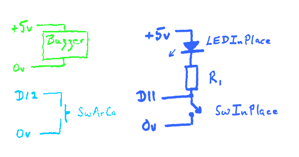
(Note the error explained in the text just above the diagram.)
A word about my abbreviations:
#define bBuzzer 9//no;
#define bArCa 12 //no;
#define bInPlace 11//no;

void setup(){

pinMode(bBuzzer,OUTPUT);

pinMode(bInPlace,INPUT);
pinMode(bArCa,INPUT);
digitalWrite(bInPlace,HIGH);//"Switch on" internal pull up
digitalWrite(bArCa,HIGH);//"Switch on" internal pull up
};

void loop(){
if (digitalRead(bArCa)==LOW) digitalWrite(bBuzzer,LOW);
  else digitalWrite(bBuzzer,HIGH);
};
That falls a long way short of "doing everything"... but it does let you test some important elements of the hardware setup. Believe it or not, it took me quite a while to get the hardware, and that software for it, just right. By the way... there's no need to install the reed switch on the door just yet unless you want lots of exercise going back and forth. And, as suggested earlier, I would, for now, use a red LED in place of the buzzer. Modules. If you do this right, a buzzer can be swapped in for the red LED later in the day. And even later, when your first buzzer dies for some reason, a well built modular design won't give you grief when you try to swap in a replacement.
With the system so far, pressing swArCa will "ring the buzzer" (turn the red LED on), and bringing a magnet near the reed switch (swInPlace) will turn LEDInPlace on. The buzzer and LEDInPlace both go off again as soon as the switch is released or the magnet moved away. (Keep that magnet away from any floppy disks (remember them?) or hard drives, won't you?)
Running quickly through the code we have so far....
#define bBuzzer 9//no;
#define bArCa 12 //no;
#define bInPlace 11//no;
These three lines define where we have connected the elements of our hardware. (LEDInPlace is driven directly by swInPlace.... the software "doesn't know it's there".) If we are disciplined, and only ever refer, say, to where the buzzer is connected with bBuzzer elsewhere in the program, then should we ever decide to connect it to a different pin, only one line of the program needs to be changed.
The #define "word" means that, in this example, "bBuzzer" means the same thing as "9" as the program is compiled. Note that at the end of a #define line you should not have a semicolon. I put the little rem "//no;" in my code on every #define line because semicolons here cause obscure errors, and the rem helps me resist fits of "tidy-itis" during which I may put a semicolon where it ought not go.
The line in "setup"....
pinMode(bBuzzer,OUTPUT);
... is just a "normal" "make that pin an output" line.
Next, consider...
pinMode(bInPlace,INPUT);
pinMode(bArCa,INPUT);
digitalWrite(bInPlace,HIGH);//"Switch on" internal pull up
digitalWrite(bArCa,HIGH);//"Switch on" internal pull up
Here we've done two things twice. We've set two pins as input.... and a moment later sent digitalWrite commands to them. That's a bit weird, if you think about it! A digitalWrite command is for sending output. And we've just said that these pins will be used for input.
If a pin has been configured for input, e.g. if we've done pinMode(11,INPUT), and then, which should seem a strange thing to try, we "set that pin high" with
digitalWrite(11,HIGH).....
The input will now sometimes read "high". It will, of course, read "high" if connected to 5v... but it will also read high, which wasn't certain before, even if it is connected to nothing You still have the alternative. You can still connect it to ground (0 volts), directly or logically, which will make the input read "low". Pretty neat. (If you don't think so, make 5 projects each with 5 simple switch driven inputs. When you've put the 25 resistors you'll need onto your circuit boards, reconsider whether the internal, software "connectable" resistors are cool.)
If you don't do a "digitalWrite(pin,HIGH)" after doing the "pinMode(pin,INPUT)", there will be no pull-up on the input.
All digital lines are inputs, without pull-ups, after an Arduino is reset.
---
Continuing on through our little "check the hardware" program, all that is left is....
void loop(){
if (digitalRead(bArCa)==LOW) digitalWrite(bBuzzer,LOW);
  else digitalWrite(bBuzzer,HIGH);
};
... which I thought needed no comment. If you are very new to Arduino programming, watch out for the "==". You use that whenever doing a test. Here we are testing what is returned from reading the pin with the Arm/Cancel button connected to it... is that input high? (If so, make the buzzer pin high, otherwise (else) make it low.)
I said "thought needed no comment". My failure to look at that code closely cost me about 40 minutes later. I thought that code said "If the button is NOT pressed then turn the "buzzer" off, otherwise turn "buzzer" on" It actually says "If the button IS pressed, then turn the "buzzer" on, otherwise turn "buzzer" off.".
EITHER sentence will create a system that does the same thing. At this stage in the development of this project, my confusion didn't have significant consequences. Remember all my warnings about knowing where you are going, etc, before you start? Because of my error in interpreting that line, and through taking quite a while to work my way through numerous "double negative" logic puzzles, I spent lots of extra time writing... and RE-writing this essay. You have been warned. (And I apologize if errors REMAIN!! Write and complain!)
"Divide and conquer" is true in several ways in engineering. The following represents only a small change from the program we had before, but it illustrates a valuable technique.
void setup(){
#define bBuzzer 9//no;
#define bArCa 12 //no;
#define bInPlace 11//no;

pinMode(bBuzzer,OUTPUT);
digitalWrite(bBuzzer,HIGH);

pinMode(bInPlace,INPUT);
pinMode(bArCa,INPUT);
digitalWrite(bInPlace,HIGH);//"Switch on" internal pull up
digitalWrite(bArCa,HIGH);//"Switch on" internal pull up
};

void loop(){
if (digitalRead(bArCa)==LOW)
  TurnBuzzerOn() else TurnBuzzerOff();
};

void TurnBuzzerOn();
{digitalWrite(bBuzzer,LOW);};

void TurnBuzzerOff();
{digitalWrite(bBuzzer,HIGH);};
Although the program is (slightly) longer, what we have introduced is worth the trouble.
The main part of the program, "loop", is now...
void loop(){
if (digitalRead(bArCa)==LOW)
  TurnBuzzerOn() else TurnBuzzerOff();
};
What we had before wasn't much more complex, but it wasn't as crystal clear as what we have now. "TurnBuzzerOff()" and "TurnBuzzerOn()" couldn't be much more clear, could they?
In or simple little exercise, we only ask for the buzzer to be turned on, or off, in one place. Imagine a program where we needed to say "on" and "off" in multiple places? Further imagine a case where the turning on (or off) wasn't such a simple matter, and in place of, say, "TurnBuzzerOn()" we had several lines of code.
Anyway... any time we can "wrap up" the details of a subordinate process in a subroutine, it is probably worth doing it.
If we need to make changes to the code for turning the buzzer on, as we will, it is easier to do that without messing other things up if the "turn it on" code is in a discrete subroutine, as it is in our second version of our program, above.
While we have things "wrapped" in subroutines, we "divide and conquer" in that when we are looking at the overall picture, and just using "turn on" and "turn off"; we aren't confronted by the code for the internal details of those chores. And if for some reason we do need to look at internal details, when we are doing that, we aren't distracted by any elements of the bigger picture.
We're now going to do something similar, to "wrap p" our test of the state of swArCa into a subroutine. This time, we are using a function which returns a value.
In "loop()", we had....
if (digitalRead(bArCa)==LOW)...
We're going to make that...
if (boArCaPressed())...
Be very careful to include the "()" immediately after the "boArCaPressed". The same line, without the "()" isn't syntactically "wrong"... it will compile without giving errors... but it doesn't mean what we want to say!!!
The "bo" prefix is for "boolean", something which is either "true" or "false". Previously, we had digitalRead(bArCa)==HIGH where we now have boArCaPressed(). Taken all together, what we had before boils down to "true" or "false".... as will boArCaPressed().
In order for boArCaPressed() to work at all, and to have it boil down to "true" or "false", we add the following to the bottom of the program....
boolean boArCaPressed(){
boolean result = false;
if (digitalRead(bArCa)==LOW) result=true;
return result;
Note that we have both a "bArCa" and a "boArCaPressed" in the program. The first holds a simple, byte-type number, hence the prefix. The latter holds a boolean value.
(An aside: Remember I said a minute ago that, due to inadequate planning, I had to go back to the start of this and re-write things? Believe it or not, I've just had to RE-re-write the essay. The problems for me arise as follows: At a fundamental level, we are dealing with "highs" and "lows". They don't always translate to "buttons pressed" or "buzzers on" as you might at first imagine. For instance, to turn the buzzer on, you bring the line low.... given the way we have it wired up. You CAN wire a buzzer so that bringing the line high turns it on. If you have parceled things up in your code as I have above, then it is easy to modify the software to compensate for the change in the hardware.)
While I wish I had got to this "base camp" a lot sooner, I don't regret the time with my "trivial" exercise to get (fingers crossed) "everything" right, in the bits we've done so far. We have "new words" to....
I was going to simply rely on LEDInPlace to tell me about the signal from the reed switch, but given the trouble I've had so far with "trivial" things, I think a proper test program is in order. We need the "new word" we are going to build, boInPlace, anyway.
My test program will be very like the one we had before. We will switch the "buzzer" on and off. We'll just use the signal from the reed switch, properly "wrapped" in boInPlace() to do it. The code for that is as follows. Because of the way we are building this, all I had to do was change one word in the four line "loop" function, and add the small bit of code at the end defining boInPlace(). (This "step forward" took about two minutes... about what the previous ones should have taken!!)
/*DoorMonJly19
ver 12 July 2010
Door monitor... subject of tutorial...
http://sheepdogguides.com/arduino/art1c.htm
*/

#define bBuzzer 9//no;
#define bArCa 12 //no;
#define bInPlace 11//no;

void setup(){

pinMode(bBuzzer,OUTPUT);

pinMode(bInPlace,INPUT);
pinMode(bArCa,INPUT);
digitalWrite(bInPlace,HIGH);//"Switch on" internal pull up
digitalWrite(bArCa,HIGH);//"Switch on" internal pull up
};

void loop(){
if (boInPlace())
TurnBuzzerOn(); else TurnBuzzerOff();
};

void TurnBuzzerOn(){
digitalWrite(bBuzzer,LOW);
};

void TurnBuzzerOff(){
digitalWrite(bBuzzer,HIGH);
};

boolean boArCaPressed(){
boolean result = false;
if (digitalRead(bArCa)==LOW) result=true;
return result;
};

boolean boInPlace(){
boolean result = false;
if (digitalRead(bInPlace)==LOW) result=true;
return result;
};
At this point we are going to start building the perhaps- more- complex- than- you- might- expect structure in the loop() function. This is to allow us to use our original flowchart/ state diagram in a state diagram mode.
Everything will work around a variable called, amazingly enough, "bState", which we will initialize with "0" (zero). That must be done outside "loop()", so that it doesn't get set back to zero at the start of each pass through "loop()".
The following, while not doing everything that our program is planned to do, and ignoring the problems of switch bounce (for now) will give you an idea of how we are going to use bState. (We do a TurnBuzzerOff(); in setup() to establish initial buzzer status.)
byte bState=0;//Put just after "#define"s at head of program
void loop(){
switch (bState) {
  case 0:{if (boArCaPressed()){
        TurnBuzzerOn();
        bState=1;}//end then of if boAr...
      break;
     };//end case 0
  case 1:{if (boArCaPressed()==false){
        TurnBuzzerOff();
        bState=0;}//end then of if boAr...
      break;
     };//end case 1
};//end of "switch" structure
};//end of loop()
And there you have it! That's "all" there is to the basic idea I want to use to build our door monitor. That little bit of code makes the "buzzer" turn on, probably just the red LED at this stage, if the ArCa (Arm/Cancel) button is pressed. And, thanks to all the hard work earlier, that bit of coding went quickly, easily.
The Arduino will, as it should, execute "loop()" over and over again, rapidly. On some passes through the subroutine, certain bits of code will get executed.... which bits will depend on the value stored in bState. Sometimes, within the different alternate actions, what is stored in bState will change.
The "break;" at the end of each "case" clause is there so that no other code in the loop subroutine will be executed before the next pass through it. There would probably be no clashes, but why take the chance?
I hope this little bit of code is clear? I will resist the urge to talk about it too much, but do write in if you feel I need to say more here.
Sadly, before we can go much further, we need to deal with the question of "switch bounce".
To our frail human senses, when we press down, say, swArCa, the circuit closes as the button goes down, and stays closed until we release the button, and then the circuit opens, and stays open until the next time the cycle is repeated.
To the computer's "eye": Not so in every case. (And you should assume it isn't so until you know enough that you'd be skimming this section!)
To the computer's prodigiously fast eye, as the switch is closing, there isn't just one closure, but many. It is almost as if the switch "stutters". (Wikipedia has... at 7/10, anyway!... a little more on the subject.)
Up to here, in this project, we've been able to ignore bounce. When, for instance, we were causing the buzzer (or red LED) to come on by pressing swArCa, what we perceived as....
Switch:  0000011111111111111111111111111111110000
LED:     0000011111111111111111111111111111110000
(That's a graph of "ons" (1s) and "offs" (0s) plotted against time, with a brief (to humans) "on" shown.)
... was actually....
Switch:  0000010100111111111111111111101010010000
LED:     0000010100111111111111111111101010010000
When it is only us "watching" the direct result of the switch's operation, the slight "chatter" at either end isn't important. However, if the computer is "watching" the switch, and changing the state the program is in as soon as it simply sees a change in the switch's state, we could have problems.
There is no simple answer to this. What you need will depend on the details of your situation.
In our case, we are using "a change" in the state (high or low) of swAr to cause us to change the "state" we are in... that word used in the second instance in a more complex way that the simple "high" / "low" of electronic signals. (We're also watching swInPlace... we'll come back to that later.)
For example, we leave the "Waiting To Be Armed" state when the ArCa button is pressed, we go to the "Guard Premises" state. While we are there, if the ArCa button is pressed again, we go back to "Waiting To Be Armed". What we would consider "pressing the switch once" the computer, due to bounce, might see as "press/ release/ press/ release"... and to us it would seem that "nothing" had happened, if we noticed we were back in "Waiting To Be Armed". (It would be hard for us to see that, by the way.)
So here's what we're going to do. We're going to make a new function called boArCaPressedDBB. The "DBB" on the end is for "de-bounced, blocking". (We'll come to that "blocking" bit in a moment. It will....
What is wrong with that picture? (Apart from it being complex? Necessarily complex. Sorry.)
For our purposes here: Nothing is wrong. But we won't be able to use boArCaDBB for the test which takes us out of "Ring Alarm". I'll explain that in a moment.
First, let me explain the "blocking" in the title of the subroutine. If you press swArCa down, and hold it down, you will stop the computer doing anything except waiting for you to release the button. You are "blocking" the computer from dealing with other things. Happily, this program was written so that it doesn't matter if the program is thus blocked... here.
A moment ago, I said we can't use boArCaDBB for the test which takes us out of "Ring Alarm". Why not?
The human who presses swArCa is going to expect the pressing of the button to turn off the buzzer. It won't. Why not?
If we use boArCaDBB, it will be the releasing of the button which lets the program leave the function, and move on to the part of the program that turns off the buzzer. What a pain!
We'll cross that bridge later. For now, let's press on with working through the state diagram.
Implied in what's gone before: When the system gets power, it will do what is in the "setup()" subroutine. It will then pass into the "loop()" subroutine, where we will have implemented something like the simple program above which is managed by bState.
In our finished latching relay program, when we go into loop() for the first time, bState will start off set to 0, and the "case 0:" code will implement "Waiting To Be Armed".
When the system gets "true" back from boArCaNBB, it will pass to the next state, state "1", "Guard Premises".
(Aside: The box saying "Later.. see text..." would have the one or both of the following in it if I could be bothered....
The first thing it might have in it is an "exit delay". That wouldn't be particularly relevant to my problem as stated, and not particularly easy to use without a few other changes, but most alarm systems have a way to let you say "Arm the alarm 15 seconds from now, after I have left the room."
The other thing that would go into the plans here, if I could be bothered, would be a test to see if the door was open the right amount to leave the alarm silent. If it was, then the system would proceed to "Guard Premises". If the door was NOT open the "right" amount, the code in the box "Later..." would somehow prompt the user to get the door right before arming the system. In the real world, I will simply look at LEDInPlace to get the door in the right place before arming the system. End of "Aside".)
In "Guard Premises", it says we go on to "Ring Alarm" if swInPlace changes. That should say "Go on if swInPlace not in right state." (The difference is subtle, and if you don't see the implications, don't worry!) Our subroutine boInPlace(), which return "true" if the door is where it should be, i.e. if it has not been moved from the position the system is watching for. Note that because we have "parceled up" the "Is it in the right place" test so nicely, that it would be easy to change the program to work properly with a different sensor, for instance a switch which OPENED when the watched object moved. (Hey! This has potential as a child monitoring system! Tell the child to stand on a push button, and if the button is released, the buzzer will sound, and let you know the child has wandered off! (Joking aside? It would be easy to set up a small radio receiver to close a switch when it sensed a signal, and put a suitable weak radio transmitter in the child's pocket.))
Oh dear. I'm getting punchy. Back to work....
For as long as we are in "Ring Alarm", we will make the buzzer buzz. While we are building the system, I'm only connecting this output to a red LED... I don't need constant noises from a buzzer, thank you.
Leaving"Ring Alarm"/"Watch for Release". Hmmm. This is a little messy.
Remember that because of switch bounce, we had problems to overcome? And we did overcome them for our earlier needs.
Here's what we're going to do in "Ring Alarm"/"Watch For Release". If it weren't for switch bounce, we could just change from "Ring Alarm" directly to "Waiting To Be Armed" as soon as we saw swArCa pressed. But because of bounce, there would be problems if we didn't "get clever", as follows....
In "Ring Alarm", we are going to watch for any time when swArCa is down two times in a row, a tenth of a second apart. That will go in the function boArCaDown(). That will be good enough to count as "pressed", and will thus move us to the "Watch For Release" state.
In "Watch For Release", the buzzer is turned off. (Or, to put it another way for when the electronics are more suited to the following statement, we will stop keeping the buzzer buzzing.)
While we are in "Watch For Release", we will monitor swArCa. Only when it has NOT been pressed at two consecutive moments, two tenths of a second apart will we consider it released. We are looking at the question this way in order to avoid being fooled by the early brief (perhaps .01 second... enough for computer to see, though) "releases" which are part of the chatter as the switch goes from truly "closed" to truly- and- finally- until- it- is- pressed- again "open". The subroutine will be called boArCaNotDown.
Whew! We made it. I really did type all of that out before starting to write the code. Fingers crossed that my plans are sound. It will make writing the code trivial. And if my plans aren't sound, not only will getting the code working be a pain, but I'll have to do heavy edits to the preceding text. Sigh.
Early in this essay, I promised that we would be able to change what turns a ringing alarm off. Pressing swArCa is not the only option. You might, in some applications of the system want, for instance, to make it much harder to "de-latch" the "relay" once it has been tripped.
Fear not! Because we took the "states diagram" approach, where we need to change the code is easy to find, and the change we need is easy to implement.
The relevant code is at....
case 2:{DBmsg("state 2:Ringing",2);
       TurnBuzzerOn();
       if (boArCaDown()){
       bState=3;}//end then of if boAr...
      break;
     };//end case 2
We need to change "boArCaDown()" to a new subroutine, say, "boCancelRinging()", and then write the code that implements our requirements. Easy!
I will press on to the summit in a moment, but first a quick word about some new code you will encounter.
Our program is becoming more complex, and more is going un "under the surface". If we want to stay sane, we need to use debugging tricks.
One of the simplest is to have a program send messages like "In 'RingAlarm' State" at the appropriate moments. That message would probably be sent to the Arduino's development environment's serial monitor, but, as we shall see in a moment, we can build flexibility into our arrangements.
You may... you should!... have noticed by now that I like to parcel things up in subroutines. I want to be able to sprinkle things like DBmsg("In RingAlarm",0); around in my code. The "In RingAlarm" text will, once I've written the subroutine, go someplace helpful, and the "0" is an alternate form of the same message. (A pretty telegraphic form... but one that could be shown on a few LEDs).
The subroutine will look like this....
void DBmsg(char sTxt[], byte bCode){
//(Not using "bCode" at this time, but present
//in case I want to alter DBmsg and have it
//output message on a small bank of LEDs
if (boSendDB) {Serial.println(sTxt);};
};
... which should mostly make sense. The only other thing you need to know is that the start of the program now includes...
#define bBuzzer 9//no;
#define bArCa 12 //no;
#define bInPlace 11//no;

boolean boSendDB =true;

void setup(){

if (boSendDB)  {Serial.begin(9600);};
DBmsg("Test of boSendDB",0);
.
.
.
(There are three new lines in that)
Simply by changing boolean boSendDB =true; to boolean boSendDB =false; (or even boolean boSendDB =!true; (I merely added the "!")), I can turn off the generation of the debugging messages... not that they much matter, anyway.
I can change what happens in every place I've inserted a DBmsg("xx"... simply by making changes in the sub-routine that posts those messages.
A if (boSendDB){delay(200);}; at the end of "loop()" will help in some ways, interfere in others. (You don't want the stream of data going to the serial monitor to flow so quickly that it overwhelms that part of the system, but the delay(200) "blinds" the system for a fifth of a second.)
Well! Finally! Here's the (almost) finished code. To create it from what we already had, I only had to re-do "loop()", and supply the subroutines boArCaPressedDBB(), boArCaDown() and boArCaNotDown().
To do that (and tidy away a little boo-boo which you don't need to know about!) took "only" 50 minutes... a great deal less time that I would have spent without the carefully laid plans.
One problem was found in those plans. If you go straight from "Guard Premises" back to "Wait To Be Armed" with only boArCaPressedDBB() to trigger the change of state, then the button is likely to be down still when you get back to "Wait To Be Armed", and you will drop straight back to "Guard".
Happily, there is an easy cure... and I don't think that is a coincidence. Carefully planned, well constructed programs not only tend to work, but are also easily modified, if you take care while modifying to continue working with the same care.
In this case, all that was needed was to "break" the line (on the states diagram, see top of essay) between "Guard Premises" and "Waiting..."
From "Guarding", in the case of ArCa being pressed, we need a line to "Watch for Release", instead of the line we've just "broken".
Implementing that change in the code was remarkably easy... because of the way we'd built it. All it took was changing what is now a "3" from a "0" in the line within case 1: of "loop()" which is marked "see text", i.e...
case 1:{DBmsg("state 1:Guarding",1);
        if (boArCaPressedDBB()){
        bState=3;}//end then of if boAr...SEE TEXT!!
Here's the almost done version of the door monitor/ latching relay program. Why "almost" done? See notes below code.
/*DoorMonJly19
ver 12 July 2010
Door monitor... subject of tutorial...
http://sheepdogguides.com/arduino/art1c.htm
*/

#define bBuzzer 9//no;
#define bArCa 12 //no;
#define bInPlace 11//no;

boolean boSendDB =true;
byte bState=0;

void setup(){

pinMode(bBuzzer,OUTPUT);

pinMode(bInPlace,INPUT);
pinMode(bArCa,INPUT);
digitalWrite(bInPlace,HIGH);//"Switch on" internal pull up
digitalWrite(bArCa,HIGH);//"Switch on" internal pull up

if (boSendDB)  {Serial.begin(9600);};
DBmsg("Testing DBmsg",0);
};

void loop(){
TurnBuzzerOff();//Establish initial buzzer status
switch (bState) {
  case 0:{DBmsg("state 0:Waiting",0);
       if (boArCaPressed()){
        bState=1;}//end then of if boAr...
      break;
     };//end case 0
  case 1:{DBmsg("state 1:Guarding",1);
        if (boArCaPressedDBB()){
        bState=3;}//end then of if boAr...SEE TEXT!!
        if (boInPlace()==false){
        bState=2;}//end then of if boIn...
      break;
     };//end case 1
  case 2:{DBmsg("state 2:Ringing",2);
       TurnBuzzerOn();
       if (boArCaDown()){
       bState=3;}//end then of if boAr...
      break;
     };//end case 2
  case 3:{DBmsg("state 3:Watching",3);
       TurnBuzzerOff();
       if (boArCaNotDown()){
       bState=0;}//end then of if boAr...
      break;
     };//end case3
  default:{DBmsg("Invalid state encountered",15);
      break;
     };//end case
/*  case :{DBmsg("state ",);

      break;
     };//end case*/
};//end of "switch" structure
if (boSendDB){delay(200);};
};//end of loop()

void TurnBuzzerOn(){
digitalWrite(bBuzzer,LOW);
};

void TurnBuzzerOff(){
digitalWrite(bBuzzer,HIGH);
};

boolean boArCaPressed(){
boolean result = false;
if (digitalRead(bArCa)==LOW) result=true;
return result;
};

boolean boInPlace(){
boolean result = false;
if (digitalRead(bInPlace)==LOW) result=true;
return result;
};

void DBmsg(char sTxt[], byte bCode){
//(Not using "bCode" at this time, but present
//in case I want to alter DBmsg and have it
//output message on a small bank of LEDs
if (boSendDB) {Serial.println(sTxt);};
//if (boSendDB) {Serial.println(bCode,HEX);};
};

boolean boArCaPressedDBB(){
  //Does... I think!... what
  //http://sheepdogguides.arduino/aht1c.htm
  //says it does....
  //Tests if a switch is pressed (bArCa==low),
  //and block processing until the bouncing
  //during switch CLOSURE should be over.
  //Line tested twice so that stray "dropouts"
  //on line will be ignored.
boolean result = false;
if (digitalRead(bArCa)==LOW) {//1
   delay(200);//See if down for more than a brief moment...
   if (digitalRead(bArCa)==LOW) {//2
       delay(200);//Give time for bouncing to end.
       result=true;
       };//2
   ;}//1
return result;
};

boolean boArCaDown(){
  //Does... I think!... what
  //http://sheepdogguides.arduino/aht1c.htm
  //says it does....
  //Returns true if (bArCa==low) twice in
  //a row, separated by a brief interval.
  //Line tested twice so that stray "dropouts"
  //on line will be ignored.
boolean result = false;
if (digitalRead(bArCa)==LOW) {//1
   delay(200);//See if down for more than a brief moment...
   if (digitalRead(bArCa)==LOW) {//2
       result=true;
       };//2
   ;}//1
return result;
};

boolean boArCaNotDown(){
  //Does... I think!... what
  //http://sheepdogguides.arduino/aht1c.htm
  //says it does....
  //Returns true if (bArCa==HIGH) twice in
  //a row, separated by a brief interval.
  //Line tested twice so that stray "dropouts"
  //on line will be ignored.
boolean result = false;
if (digitalRead(bArCa)==HIGH) {//1
   delay(200);//See if down for more than a brief moment...
   if (digitalRead(bArCa)==HIGH) {//2
       result=true;
       };//2
   ;}//1
return result;
};
What you see above it pretty good. It "works". It would, I think, deserve an "A" as an answer in an exam.
However, when I went to install the system, to use it in the real world, a couple of things cropped up. I'm not going to do full tutorial notes on all of the implications, but I will give you the "final", "real world" version of the project, below.
But I will give you some indications of the differences between the penultimate version and the final version.
It dawned on me, duh, that the user should be given some indication of whether the alarm is armed. So I added another LED, a green one on D10. As with most, the "top" of the LED goes to 5v, then there's the current limiting resistor, and the other "side" of the LED/ resistor goes to the Arduino's pin. So pulling the output LOW turns the LED ON. This is a little illogical (low=on??), but it is "buried", "wrapped up" in the two subroutines "ArmedOn()" and "ArmedOff()"... i.e. the subroutines which turn the "Armed" LED on and off.
Actually, a single routine called "ArmedLED", which you would pass a 1 or a zero to, to turn LED on or off, would be more elegant... but in this tutorial I try to avoid "tricky" things that might distract my least experienced readers.
These new sub-routines are used in the loop() code in a way we haven't made use of before. If you look, say, at the "case 1:" handler, you'll find the "ArmedOff()" in the bit of code that is executed the last time the program passes through the "case 1:" code before switching states.
There was an unwelcome little "feature" in the penultimate version of the system. If it was in state 0, "Waiting To Be Armed", and a user depressed swArCa, the Guarding state was, as planned, entered. However, it the user left the button down too long, the system (obediently) went on to state 3, "Watch for Release", "thinking" that the user wanted to cancel the arming which had just been accomplished.
Sticking...
while (boArCaPressed()){};
while(boArCaNotDown==false){};
... in where I did in the exit from state 0, in "case 0:", fixes things... I think... even if it does so a little in-elegantly.
All through my testing, I had an LED "standing in" for the buzzer which is going to "shout" if the door moves when it shouldn't. I had a red LED on that output, red for "danger", whatever.
And I wired it the way we usually wire LEDs. Bringing the output LOW turned the LED ON.
Turns out that the buzzer I want to use us turned OFF by the output being LOW.
Fixing all that wasn't really terribly difficult... because the details of the buzzer, be it real one or LED stand in, are "wrapped up" in the subroutines "TurnBuzzerOn()", "TurnBuzzerOff()"... but for a polished, consistent text, the tutorial above would need extensive re-writes... so just....
The programming of the buzzer in the "real world" example is "backwards" to the wiring of it elsewhere in the tutorial. If you want to use an LED on the line, and have it on when the buzzer is on, this is easily accomplished, AS LONG AS you change the connection of the LED so that its "top" comes from the Arduino output pin, and, via the LED and current limiting resistor, the circuit goes to the system ground, zero volts.
Funny... there have been problems relating to this all though my work on this tutorial... I've spared you some of them.
Buzzer: I am very happy with the little module I bought from nuelectronics.com for about $4 + sensible p&p, 7/10. It connects to Vcc and gnd, and then a third wire is taken to an Arduino digital output. If the output is high, the buzzer emits a good, continuous, "squeak". Output low: buzzer quiet. In other words, the module has a built in oscillator, and the current to drive the piezo element isn't all flowing though the Arduino output pin. Any you don't have to generate a square wave to get a continuous noise from the buzzer. (Yes... the wiring diagram at the start of this essay is wrong, if it still says the buzzer is just connected to 5v and 0v.)
One final point about buzzers: Some are just a piezo element. If you use one of these, the program, as it is below, won't "work". The buzzer, when on, needs a stream of "on/off"s. These can either be achieved via the Arduino's ability to send PWM signals (not hard to arrange, but a story for another time!) or by inserting into the "case 2:" "Ring alarm" code something to bring bBuzzer high briefly, and then put it low. As "loop()" is executed over and over again, this, especially if you turn off the messages to the serial monitor, should suffice to give rise to a suitable stream of ons and offs to make the buzzer buzz.
So! Here's the Final version! Enjoy!..........
/*DoorMonJly19
Full code.
ver 13 July 2010
Door monitor... subject of tutorial...
http://sheepdogguides.com/arduino/art1c.htm
*/

#define bBuzzer 9//no; LED/Buzzer: High for on
#define bArmed 10//no; LED: LOW for LED on
#define bArCa 12 //no; Momentary to gnd
#define bInPlace 11//no; Momentary to gnd

boolean boSendDB =true;//Set true to enable debug messages
                       //to serial monitor
byte bState=0;

void setup(){

pinMode(bBuzzer,OUTPUT);
pinMode(bArmed,OUTPUT);
TurnBuzzerOff();
ArmedOff();

pinMode(bInPlace,INPUT);
pinMode(bArCa,INPUT);
digitalWrite(bInPlace,HIGH);//"Switch on" internal pull up
digitalWrite(bArCa,HIGH);//"Switch on" internal pull up

if (boSendDB)  {Serial.begin(9600);};
DBmsg("Testing DBmsg",0);
};

void loop(){
switch (bState) {
  case 0:{DBmsg("state 0:Waiting",0);
       if (boArCaPressed()){
         ArmedOn();
         //Next two lines "trap" execution here
         //Until buArCa released, so that
         //if a user's finger lingers on
         //buArCa, the system doesn't go back
         //to waiting after it starts guarding.
         while (boArCaPressed()){};
         while(boArCaNotDown==false){};
         bState=1;}//end then of if boAr...
      break;
     };//end case 0
  case 1:{DBmsg("state 1:Guarding",1);
        if (boArCaPressedDBB()){
        ArmedOff();
        bState=3;}//end then of if boAr...SEE TEXT!!
        if (boInPlace()==false){
        bState=2;}//end then of if boIn...
      break;
     };//end case 1
  case 2:{DBmsg("state 2:Ringing",2);
       TurnBuzzerOn();
       if (boArCaDown()){
       ArmedOff();
       bState=3;}//end then of if boAr...
      break;
     };//end case 2
  case 3:{DBmsg("state 3:Watching",3);
       TurnBuzzerOff();
       if (boArCaNotDown()){
       bState=0;}//end then of if boAr...
      break;
     };//end case3
  default:{DBmsg("Invalid state encountered",15);
      break;
     };//end case
};//end of "switch" structure
if (boSendDB){delay(200);};
};//end of "loop()"

void TurnBuzzerOn(){
digitalWrite(bBuzzer,HIGH);
};

void TurnBuzzerOff(){
digitalWrite(bBuzzer,LOW);
};

boolean boArCaPressed(){
boolean result = false;
if (digitalRead(bArCa)==LOW) result=true;
return result;
};

boolean boInPlace(){
boolean result = false;
if (digitalRead(bInPlace)==LOW) result=true;
return result;
};

void DBmsg(char sTxt[], byte bCode){
//(Not using "bCode" at this time, but present
//in case I want to alter DBmsg and have it
//output message on a small bank of LEDs
if (boSendDB) {Serial.println(sTxt);};
//if (boSendDB) {Serial.println(bCode,HEX);};
};

boolean boArCaPressedDBB(){
  //Does... I think!... what
  //http://sheepdogguides.arduino/aht1c.htm
  //says it does....
  //Tests if a switch is pressed (bArCa==low),
  //and block processing until the bouncing
  //during switch CLOSURE should be over.
  //Line tested twice so that stray "dropouts"
  //on line will be ignored.
boolean result = false;
if (digitalRead(bArCa)==LOW) {//1
   delay(200);//See if down for more than a brief moment...
   if (digitalRead(bArCa)==LOW) {//2
       delay(200);//Give time for bouncing to end.
       result=true;
       };//2
   ;}//1
return result;
};

boolean boArCaDown(){
  //Does... I think!... what
  //http://sheepdogguides.arduino/aht1c.htm
  //says it does....
  //Returns true if (bArCa==low) twice in
  //a row, separated by a brief interval.
  //Line tested twice so that stray "dropouts"
  //on line will be ignored.
boolean result = false;
if (digitalRead(bArCa)==LOW) {//1
   delay(200);//See if down for more than a brief moment...
   if (digitalRead(bArCa)==LOW) {//2
       result=true;
       };//2
   ;}//1
return result;
};

boolean boArCaNotDown(){
  //Does... I think!... what
  //http://sheepdogguides.arduino/aht1c.htm
  //says it does....
  //Returns true if (bArCa==HIGH) twice in
  //a row, separated by a brief interval,
  //indicating that button is not down. Used
  //to know when a "release" has happened.
  //Line tested twice so that stray "dropouts"
  //on line will be ignored.
boolean result = false;
if (digitalRead(bArCa)==HIGH) {//1
   delay(200);//See if down for more than a brief moment...
   if (digitalRead(bArCa)==HIGH) {//2
       result=true;
       };//2
   ;}//1
return result;
};

void ArmedOn(){
digitalWrite(bArmed,LOW);
};

void ArmedOff(){
digitalWrite(bArmed,HIGH);
};
One last little thought for you: All of my "test the switch's state" subroutines should be re-written. They should acquire an additional parameter, of type "byte". And then within the subroutines, that should determine WHICH pin's status is examined.
Here's what boArCaPressed() would look like....
boolean boPressed(byte bWhichPin){
boolean result = false;
if (digitalRead(bWhichPin)==LOW) result=true;
return result;
};
... and you could call it with, say, boPressed(bArCa);
But, for this program's needs, you don't to do that. Whew. But it makes the subroutine much more generally useful, at very little "cost".
If you visit 1&1's site from here, it helps me. They host my website, and I wouldn't put this link up for them if I wasn't happy with their service.
Click here to visit editor's Sheepdog Software (tm) freeware, shareware pages.
Click here to visit the homepage of my biggest site.
Click here to visit the homepage of Sheepdogsoftware.co.uk. Apologies if the "?FrmAht" I added to that link causes your browser problems. Please let me know, if so?
![]() Page tested for compliance with INDUSTRY (not MS-only) standards, using the free, publicly accessible validator at validator.w3.org
Page tested for compliance with INDUSTRY (not MS-only) standards, using the free, publicly accessible validator at validator.w3.org
....... P a g e . . . E n d s .....