 Recommend to StumbleUpon
For a long time, I have wanted to power small computer projects with solar power. And have them run though the night off of a battery. But it really isn't as simple as you might hope.
Project status: A unit has been assembled and tested. Works as expected. Exhaustively tested, under all scenarios? No, of course not. But basic "stuff" seems to work as advertised.
The biggest "problem" with this lovely solution: It won't power very much "all through the night"... but it seems, generally, to do what it says on the tin. More on this in a moment.
Rather late in the day, I realized that in many places I speak of the circuit as a way to use solar power. It is, in fact, a good solution for getting over the gaps in any supply that is intermittent. So if you have a project normally powered from, say, a USB charger, but which needs to move from A to B once in a while, or is at a site with occasional brief failures of the power to the charger, this circuit is for you too!
Reading for first time? You won't need this "menu" yet. But may be of use to returning visitors. Each link will open in new tab or window... just close to return here.
Getting one: I've put further detail on the "Status and Ordering" page (link: above). In a nutshell, for now: You get the PCBs from me, and I may be able help with parts. Worst case: $14 for TWO (bare) boards, incl p&p. You might be able to buy one, and you might be able to pay less, depending on postage costs.
I went back to the problem of using solar power again, older and wiser, in November 17, and found a fantastic page by Nick Gammon, full of many possibilities.... some of them independent of "the whole package". (The power supply is just one part of his bigger project: A unit to send sensor data to a base station.) The page you are reading is mostly about a PCB to implement his power supply circuit. Takes raw voltage coming from an intermittant supply (he was using solar panels), makes it "circuit friendly". Charges a "battery" for supply interruptions, e.g. overnight if the supply is from solar panels. Implements watchdog reset.
Even if you don't want the PCB this page is all about, which implements the Gammon circuit, do study his page, for the splendid ideas it may inspire in you.
Great news? Not expensive! Probably about $10 + p&p for "bits and pieces, including the PCB. To this, you need to add a supercap... $5?... and a solar panel or two...$5?. Plus of course whatever it was you wanted 24x7 power for.
The best thing about Nick's circuit is that it gives you "battery backup"... without the hassles of lipo or other "batteries" in the traditional sense of the word. A supercap is used, which has far fewer vices.
It has to be said, however, that the supercap solution will not, easily, give you a lot of battery backup. (For more on this, see my "Testing PCB 269" page)
The PCB discussed here, based on the Gammon circuit, gives you a power supply which runs from a solar panel or other sometimes-on/ sometimes-off source. (This voltage is called "Vin" in this discussion.) The PCB has a super-cap to get you through the night, and a watchdog circuit which generates a "reset" signal for the system you are powering. It generates that once after each failure of Vin. (This is to overcome processor lock-ups which can arise when the voltage to a microprocessor has been below the processor's minimum.) There is an optional 3v3 output, regulated, and a second output to run a "5v" Arduino (or other). Th 5v is not regulated, and swings widely... but not more than an Arduino can tolerate. (A "5v" Atmega 328 based Arduino will run on voltages from 1.8 to 5.5... and of course, there are the 3v3 Arduinos.) (This voltage is called "Vout" in this discussion.)
The limitations? The circuits you power must not draw much current... unless you can solve the issues relating to "big" supercaps, and unless you buy big solar panels. (But you can start with a $5 "bargain" solar panel from eBay, though!)
Another use of this circuit is to provide a "bridge" to get a system across that tiresome "gap" which some people with unreliable public electricity and emergency standby generators. When the public supply fails, there is often a brief moment of no power before the generator takes over. And another dropout when public power is restored. PCB 269 would be good for bridging the gap... you would just use an ordinary USB charger, powered by the public/ generator supplied volts, to supply PCB 269's Vin. For such short periods without power on Vin, you could power a more current hungry system without having Vout from PCB 269 fall too low.
The circuit in question was originally designed to power, 24x7, without human assistance, a small data collecting system, which sent the data collected over a radio link to a "base station". Adding the radio-equipped Arduino would add about $15 to the project, at a rough guess. (All the details of that, too supplied at Nick Gammon's page, to which I've already sprinkled enough links throughout this page.)
Nota Bene: I don't know much about some important issues relevant to this circuit, so please be particularly aware of my usual disclaimers. In particular, I have almost no experience of supercaps, and one is at the heart of this circuit. The good news is that the circuit was designed by someone who knows a lot. All I did was implement the circuit in a PCB. But along the way, I've made some substitutions, perhaps poor ones. (You can reverse my substitutions easily enough, if you can source the parts! Or if I buy some in, as I hope to.)
Be sure to read the "I read it on the internet" bit on PCB 269's main page about things you need to remember when working with supercaps.
"I read it on the internet": I read several things about supercaps on the internet, which may or may not be true. Most are "Duh, we know" type things... but what I think what was being said was "be particularly careful in these areas..."
a) Do not insert a supercap "backwards" in a circuit. Be careful that any voltage applied across one is done with the positive side of the voltage going to the positive pin of the supercap.
b) Do not exceed, even by a little bit, the rated voltage of a supercap. Do not apply 5.6 volts to a supercap only rated for 5.5 volts.
It may seem that I try to do exactly that with the circuit and components given. However, between the 5v6 zener (D1) and the supercap (C1), there is another diode... D2. As long as you stick to the 1N4148 of the original design, you should be okay... I think. It is up to you to check that this is true, if you want to use what is here.
c) Be careful: When fully discharged, they will, until some charge accumulates, show almost no resistance... so if the charging voltage is supplied by something capable of high currents, a high current will flow, unless that current is somehow limited. (That limitation is provided for in PCB 269).
d) Supercaps can also, some say, produce high discharge currents into a low resistance circuit. If you connect a low resistance circuit to the (nominally) "5v" output of PCB 269, that may be powered by C1, and thus could experience high current flows... perhaps flows higher than the supercap, or other circuit elements should experience.... so be careful! As PCB 269 is intended for low demand circuits, it seems unlikely that you would, normally, connect a low resistance path from "5v" to ground, because PCB 269 could not power such a thing for long when Vin (Once called "Vsolar", a term that may still appear here, but is being written out. The voltage from the solar panels, or whatever is the ultimate source of power for this PCB and the devices powered by it) was absent.... but just be aware that not only is it unlikely you would want to, but also a bad idea to do it, on other grounds.
e) When working with this circuit, remember the point of it: It stores power. It will not be "dead" as soon as you disconnect it. Remember that the supercap will often be holding a charge. A short circuit across its terminals would probably be A Bad Idea. A 200ohm resistor across ground and Vout for 10 seconds or so will not fully discharge the supercap, but it will bring the voltage in it down considerably.
I'll give you much more detail further down the page, but, to start this off, here's an overview:
PCB 269 is a circuit board with the right "bits and pieces" to allow you to connect a solar panel to an Arduino. The board also provides a regulated 3v3 which can supply up to 150mA. (It was used to power the radio module, in the circuit's first usage.)
Let's start our discussion from a "running" system, mid-day. The sun is shining, the solar panels are generating a voltage. That voltage is running the Arduino and things connected to the 3v3 output. The supercap on PCB 269 has charged up, ready for some clouds to pass over the sun, or for nightfall.
Come nightfall, of course, the solar panel stops generating electricity. Through the hours of darkness, the Arduino, etc, are powered from the charge stored in the supercap. If the designer has been careful, and not asked too much of the supercap installed in PCB 269, there should be enough charge to keep things going through the night. Although the 5v Arduino connected to thenominally "5v" output of PCB 269 would operate properly down to 1.8 volts (if this is an Atmega 328 based Arduino), the voltage regulator supplying the 3v3 needs a bit more than 3v3 to produce the 3v3... so if you are using the 3v3 output of PCB 269, you have to use less power to get through the night that someone who wasn't needing the 3v3 would be able to use.
And another day starts, and all is well.
But.
There's always a but.
What if you have several very overcast days in a row?
Yes, eventually the supercap "battery" would be so discharged that the Arduino would stop running. Sigh.
Oh well. When the sun returns, the voltage will gradually rise, and eventually, it will start up again... won't it?
Well... usually... yes!
But. (That word again.) Not always.
Microprocessors don't like it when their Vcc arrives slowly. Sometimes they "lock up" when the voltage applied to them rises slowly. This is called a "brownout lockup", even thought "brownup" would be a better term. The microprocessor doesn't lock up during the decline through "brown" (lights- limited voltage) to "black" happens. It happens as the voltage rises from "black" (lights), through "brown" and forward to "white", i.e. sufficient voltage for the microprocessor's normal operation.
Whatever you call it, the lockup is a pain. At least it isn't permanent. If you use the reset input, or cycle the power of the chip, it will start running normally for you.
But the designer of the circuit didn't want to have to rely upon a human to do the reset thing when needed. So he added what's called a "watchdog". That watchdog is part of PCB 269.
The watchdog is created in a little chip called and ATtiny. It can be programmed with the Arduino IDE, and in many respects is "a little Arduino". But it is very cheap, very simple... and quite limited. But not too limited to be our watchdog.
By "setting fuses" in the ATtiny (not terribly difficult), it can be configured to refuse to "wake up" until a certain voltage is reached, and that's what the one in PCB269 has had done to it. It only wakes up when the voltage applied to is rises to 2.8 volts. This comes from the same place as the power feeding the Arduino powered by the "5v" output from PCB269. That Arduino may already be working sensibly, or it may be in a "brownout lockup". In any case, the voltage is now high enough that if it is reset, it will "behave", run "properly".
And the watchdog circuit does exactly that... thirty minutes after it has come to life, because the voltage is at or above 2v8, in other words, long after the voltage from PCB 269 is "okay" again after the "discharge event", the watchdog sends a 10ms pulse out on it's reset line. (The ATtiny then shuts down until the next time it comes to life after there's been a voltage failure.) The ATtiny's reset line supplies the "/Reset" output of PCB 269, which should have been connected to the Arduino's /Reset input, and thus the Arduino is reset, at a sensible time, after any loss of voltage. Brilliant! Onward to the details...
Just in case this page hasn't "started " enough "hares", let me also mention Nick's page about power saving techniques for microprocessors. The poser supply which is the main topic of the page you are reading doesn't have a huge capacity. You can "make it do more", if you are clever with whatever you hook up to it. (The power supply was originally designed for a small system to send sensor readings to a base station via a radio link. That is also covered at Nick's page.)
A quick "nota bene" before we go any further: REMEMBER: The whole point of this board is that it stores power. If you are using one, don't treat it as "dead" just because you have disconnected Vin... it will usually have some charge stored in the super-cap. Before working on the board, discharge C1, using a suitable resistor across Vout and ground. (Why not just short? You might cause currents in the supercap which are high enough to damage it.)
Eventually, it will, I expect, be easy.
As of 02 Dec 17, I've assembled one instance of the circuit from the first batch of PCBs (ver 17b06). It "worked"! (Details elsewhere.)
Serious people, with a reputation at http://forum.arduino.cc or similar, are invited to get in touch, if you'd have time, now, to test copies of the board.
When the inevitable little (or maybe not so little!) tweaks have been taken care of, the idea is to make the boards "freely" available. (Details at Status and Ordering page. (Near bottom, when I wrote this!)
I'll try to list the different things you could build with what's at that page. Then I will go on to discuss a PCB that I am making to let you have 24x7 power supply more easily.
Note: This design is NOT going to power your big PC. It won't even power an Arduino (for long, overnight) if you haven't chosen how it operates and what it is driving to keep power demands low. But! For many things, it is Just The Ticket. And, as I said, you can "pick bits out" of the page. To wit....
A simple power supply for Arduino or other: Provides both 5v and, optionally, also 3v3. The 3v3 is regulated. The 5v is never exceeded, but may "droop" in some circumstances. (The 5v Arduinos will still run at 4v9... and lower. Some of the details of that among the many gems on Nick's page.)
This simple power supply would typically be supplied with the voltage it will then regulate from solar panels. I don't think there's anything to stop you from using other sources, especially in the "testing" phase. Or maybe you're going to use a different answer to having power night, day, and through power cuts... the backup unit common in most burglar alarms, for instance? (I'm not sure the max input voltage that is advisable. Study the datasheets! Substitute components!
"Battery backup": Lipos are a bit like quantum physics... If you think you understand designing with them, you probably don't, yet. And mistakes can be dangerous. And even if you do understand them, working with them can be a pain.
So what can you do?? Substitute a super cap as the "battery" to see your power supply over the night, if it is being powered by solar panels, or multi-hour power failures if you're using the public electricity supply.
The can't rival the capacity of a lipo, of course, but I did tell you that this design was created to power low demand systems, didn't I? If your power requirements are low, the answer can be (relatively) simple.
Brownout lock-up management: I hadn't even realized this was necessary. And got a headache trying to figure it out. And I was scared off by mention of having to program an ATtiny85.
None of those "problems" are real!!!... as I will try to make clear later.
First: What is the problem we are trying to solve?
If you are running an Arduino on a power supply with a gradually decreasing voltage, eventually it will get too low for your poor struggling, noble, will put up with many things, Arduino. This is called a "brownout", and is especially hard on microchips.
After a brownout, perhaps especially if power comes back gradually, as it may with the circuit described here (suppose you have three days of heavy cloud??)... After a brownout, the Arduino may not restart as you might hope. It may "lock up". Not forever, happily, but it won't always "just start working again" without help.
The Gammon circuit solves this problem with something called a "watchdog". If power has been lost, then AFTER it is restored, and has reached a satisfactory level, the watchdog will "press the reset button" on the Arduino, which will get it out of any lock-up it may have entered. The watchdog isn't, at first glance, terribly clever. It is build in an ATtiny, and merely cycles a line on/ off/ on (or is it off/ on/ off?) a few moments after the ATtiny is powered up, and then it just sits there, assuming all is well. But the lock up we are trying to provide protection against is one that can occur while the big Arduino powered by this PCB is powering up. Nick has tapped into some of the features of the ATtiny to make sure that the cycling of that output line only happens after the other Arduino already has more than enough voltage to behave itself, going forward. If it subsequently locks for other reasons (a bit of bad program?), then this watchdog won't get you out of the problem.
Learn to use ATtinys: Even if no part of Gammon's circuit meets any of your wants, I hope you will explore playing with ATtinys. It ISN'T hard, and costs very, very little.
I spent a few days getting "up to speed"... and then shook my head. It is NOT hard... I just had trouble finding the information I needed. Also, you don't have much to buy, if you are already "an Arduino person". I wrote Yet Another Guide to Playing with ATtinys, in hopes that you will have an easier time getting started than I did. REALLY! It is NOT hard. (You will have to buy an ATtiny to play with! To follow my guide, buy an ATtiny85... it will cost you... wait for it!... about $3!!
An ATtiny is almost an "Arduino"! And only needs some electricity to run... no external crystals, etc, needed. Cost? About $3 each. Re-programmable. Admittedly, they only have 5 GPIO lines, but they will do serial data, and other clever things. And you can program them via the Arduino IDE.
When I was trying to enter the very promising world of ATtinys, the following were extremely helpful: excellent "Getting started with ATtiny" from HobbyTronics.co.uk, which opened my eyes. This solution uses a "proper" Arduino to program "naked" ATtinys... i.e. ATtinys with no bootloader in their memory. You have to connect 6 wires between Arduino and ATtiny. (It would be easy and worthwhile, to make up a little shield, with an 8 pin DIL socket on it, if you were going to use this "answer" often. And then there was dntruong, where I learned how to read and set the fuses using the same hardware set-up! He also offers pointers to a different(?) set of software for programming "the Hobbytronics way"... a set that allows you to do fuses as well as doing the programming... If I've understood everything properly!! And also the guide to programming ATtinys from "High-Low Tech". Thank you everyone!
It also is worth a visit to Nick Gammon's fancier solution to programming ATtinys.. and more. I found it a bit over-whelming, at first, but if you scroll down, you'll see that the setup for doing ATtinys isn't too terrible, and the fuse setting matters are also taken care of. (And you'll be able to do fancy things with a bunch of microprocessors. It may be an elephant gun, if you just want to program a few ATtinys... but if you take the trouble to master what's there, you'll be "done" in that department for years, and I suspect it will pay dividends, in "opened horizons". Another source of info in this area: Dr. Azzy's pages. I THINK he lets you put a bootloader into an ATtiny, after which, you can program it directly, from the IDE.
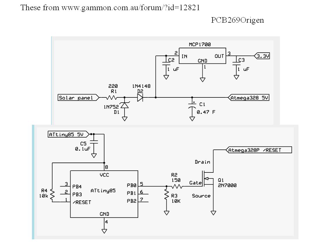
I'm now going to look a little more closely at the three elements of the circuit Nick has designed for us. (I'm not discussing the circuits he was driving with his power supply... but don't forget about them.. they're also fun and useful... but not part of PCB 269.)
Here are the circuits that Nick devised....
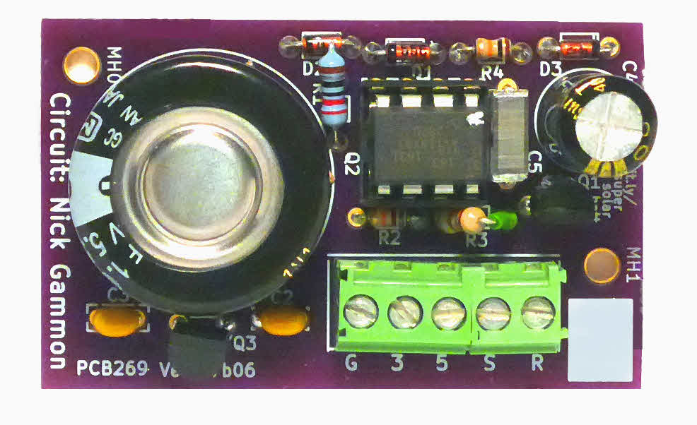
Images of the first version of PCB 269 from OSH Park, who make my PCBs for me. As of 24 Jan 18, three copies of this design existed. They were marked A, B and C (on the plain rectangle of silkscreen at upper right, top side, provided for that purpose). "A" was populated. B and C probably won't be. ("A" worked fine. But design moved on.)
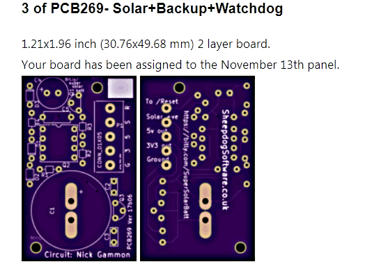
A second version was created in late November 17. At 24 Jan 18, there are three copies, again A, B, C. The board carries "PCB269 v17b28". It was just minor tweaks, enhancements, if all went well!
This section combines advice on choosing parts, and assembling the pcb.
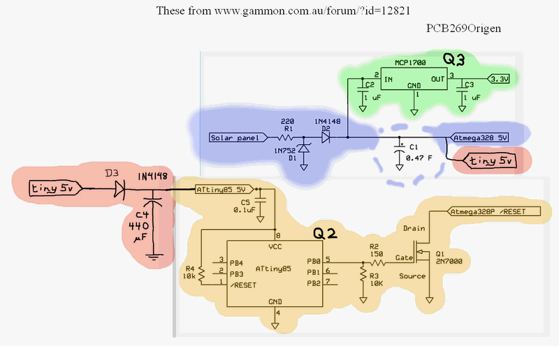
The blue section: The blue section, (R1 etc), on its own, doesn't do a lot, but it does moderate the voltage coming from the solar panels. I've put a dotted line around C1, the super-cap, because you could leave that out, if all you wanted was to restrict the voltage appearing at "Atmega 329 5v". N.B... that is a NOMINAL 5v... it will not be closely regulated to near 5v. But the Atmega, which it is designed to power, does not need a closely regulated 5v.
The green section: The green section, (Q3 etc), is to supply a regulated 3V3 for other things you may wish to power with the circuit. Nick Gammon devised this the whole circuit in connection with a small Arduino system to send some sensor readings to a central Arduino over a radio link. The radio transmitter needed 3V3. (This is all explained his huge forum post, from which these "cherries" were "picked".) If you don't need the 3V3, you can leave these components out... and increase the unit's ability to carry your project across a time when the solar panels are not producing the voltage you need.
The red/ orange section: The red/ orange section, (D3, C5 etc), is all about implementing the watchdog, which sends a reset signal to the Arduino this power supply was designed for. The red parts were drawn in by me from things indicated at Nick Gammon's page. The orange parts were on his page as you see them. You would want all of the red and the orange bits... or none of either.
Gather the components you intend to put on your board. Note: If you are including watchdog circuit, you will need to program the ATtiny85, and have to right fuse settings established in it. (The details of the program, and the fuse settings, are at Nick's page, and also at a copy I took, 1//17. I'd go to Nick's, if I were you... mine is only there in case his ever disappears. He may have updated it since I took my copy, November '17.) (New to ATtinys? You'll have to learn about the 3 fuse bytes. The contents of those 24 bits configure how the chip behaves. (Another form of programming, really. Do-able. See other material elsewhere in this page.
Before you solder in anything, take a multi-meter and make as many checks on the board as you can be bothered with.
Two quick asides:
a) At all times, unless I've been very clear that "the usual" does not apply, I am speaking of things as if looking at the "top" side of the board. The side all the components go on. The side with "Circuit: Nick Gammon", and the small rectangle of blank silkscreen which is there so that you can mark individual instances of the circuit with some sort of serial number or other identifier. And "up" will be towards C4 and the rectangle of blank silkscreen, "down" being towards the big circular footprint for the supercap. "Right" is the edge with the 5 way strip of screw terminals.
b) i) The voltage provided from the board is referred to as "Vout". It can be as high as a little less than 5v6. It will gradually decline, in a linear manner with a constant load, when no power is going into the board. (At one stage, I was calling this voltage "5v", and the circuit schematic still calls it "ATtiny85_5v" to be consistent with the circuit designer's notes... but don't be fooled by the "5v". It isn't a constant 5.00 volts. But! Many Atmega chips run over a wide range of voltages, so a range of voltages from PCB 269 doesn't have to be a deal-wrecker! I am trying to write any references to "5v" and "nominally '5' v" out of this page. Apologies for those that remain.)
b) ii) In a similar vein, I once referred to the voltage supplied toPCB 269, nominally from solar panels, but of course it can come from anywhere, as "Vsolar". The original circuit calls it "Solar panel" in some places, and "V Batt" crept in in a few places in my diagrams. The "new name" for this is Vin, and I am trying, as with "5v"/"Vout" to clean things up. (Part of the reason for the change was that on the screw terminal labels, I had "5" and "S" to mark the two voltages. I didn't like the chance that "5" would be understood to mean "this should be close to 5v", and the two characters (5 and S) are a bit too easy to confuse with each other. So now you know.)
Things to try:
Depending upon your confidence in the design of the board, and your identification of the parts, there are two paths you can follow. Just before you begin assembly, give the PCB a good clean. I like to give it a gentle polish with some fine steel wool after a final solvent wash to remove oily finger marks, etc. The cleaner the copper is when you go to solder things to it, the easier it will be to get a good result.
If your components are fresh and new, you probably don't need to do what I'll mention now... but if they've been in your stocks for ages, a little oxidation may have built up on the leads. A bit of delicate scraping can be worth the trivial effort.
If you lack confidence, build it in stages, testing as you go along. For instance you might do the blue section first, then add the green, then finish.
Probably better to just "go for it", though.
Whichever approach you use, postpone inserting the ATtiny (Q2) in its socket until you've done all the tests you can be bothered with on other parts of the assembled board. This will not affect other things... unless an "unfed" mosfet (Q1) is a problem? I'm hoping... let me know if you know, please?.. it will "behave". I'm hoping that with R3 to pull the gate low, it will be irrelevant?
If you decide to "just go for it", install the small, fiddly bits first... the diodes, small capacitors, resistors. And then the larger bits. But while fitting the small bits, if they crowd something bigger, put it in place, make sure the space it needs won't be impinged upon. But solder the little guys first. (The design is a work in progress. At the moment, some of the resistors crowd the 8-pin DIL socket, for instance.)
Take care with polarized components. (The ones that have to be inserted "the right way around".)... viz...
In My Perfect World, all of the resistors would be 1/8th watt... apart from R1. 1/4 watt is probably "overkill" here, but, in theory, briefly, this resistor could be dissipating more than 1/8th watt. (I used a 1/4w resistor for R2 in instance "A" of the version 17b28 board for the uncomplicated reason of not having a 1/8w 150 ohm resistor at the time!)
Be careful, at least with boards though vers 17b28... D2/D1/R4/D3 are laid out in a column. The space between pads is not quite sufficient. D2 is supposed to connect to D1, but in no other cases of adjacent pads should there be a connection. Beware "solder bridges".
Don't install the socket or chip for Q2 rotated 180 degrees from its correct orientation! The socket should have some marking to indicate the end for P1. (P1 should be at the end farthest from the large position provided on the PCB for C1.) The IC will usually have a small dimple near pin 1, or a "groove" along the side with pins 1-4. Beware the chips that have TWO dimples. Look to see if yours has two, and use the larger, more obvious one to "count" as the one marking P1.)
With Q1 and Q3, be sure the correct legs go to the pads they should, ESPECIALLY Q3! (For Q3: In the first boards, v17b06, there was a mistake in the silkscreen guidance. In the second boards, v17b28, provision was added to allow you to use either of two components for Q3... components with different footprints! (See "my page 'Versions of PCB269'". That page will open in a new tab or window. Close it to get back here.)
If you are assembling a kit of parts, take time now to be sure that you know which is which. There are few things more annoying that soldering in 9 out of 10 parts, and then discovering that the remaining part looks all wrong for the remaining position.
Many parts vary in appearance from one supplier to another.
At the time of writing, the board is designed for 0.125W resistors, but in a few cases I only have 0.25W resistors... physically a little larger. They can be used; you just leave one end a little high, with the body or the resistor diagonal to the plane of the PCB. Color bands tell you the resistance of the resistor. Start with the one closest to an end of the resistor. (The body color is meaningless.) STOP PRESS: At R1, you should use a 0.25W resistor.
The diodes usually have tiny characters on them to tell you the 1N4148s from the zener diode (D1). The ones I had for the first batch of PCB 269 parts kits had BZX55c5v6 on the one for D1, and 1N4148 on the ones for D2, D3.
Elsewhere, I've written quite a large section about parts substitutions I made while implementing Nick Gammon's circuit. They probably affected performance. In all cases, you can build PCB 269 with his parts.
long the way of discussing the substitutions, quite a few design issues are covered.
You are unlikely to get exactly the supercap he used. And you may want to do substitutions yourself. I commend the material to you, but moved it to the Status and Ordering PCB 269 page. The link will open that, at the right place, in a new window or tab. Just close that to come back here.
I hope, eventually, to offer an easy way to order kits of parts. They aren't expensive, but it is nice to know that you have a strip of screw terminals which fits the footprint on the board, and having to place an order with a supplier for one resistor you don't happen to have is a major pain, isn't it?!
The official parts list for PCB is useful for more than just ordering. There are notes there about various things. The list resides in the PCB 269, solar backup "Parts list" section of the PCB 269 Status and Ordering page, which opens in a new window or tab if use the link. Just close that to return here.
This section is not complete.
Introduction to "Maximums/ minimums": Here I will try to discuss some important maximums and minimums. How high can the voltage coming from the solar panels be? How low can the voltage out on the nominally"5v" line be?
You can skip over this section, if you wish!
If you operate at either a maximum or a minimum, you are pushing your luck. It is not a good idea to be at either. You "should" "get away with it"... but so much better to operate a little below a maximum, or a little above a minimum. For a whole bunch of good reasons... and a few not "good", but still valid, reasons!
There may well be flaws in what you see in this section. I have "shown my work", not only to help people who know even less about this important topic make progress... but also to invite criticism from the many people who know more about these things than I do! (If you do write in, please quote the page's URL ("PCB269-SolarWBackup.htm" is enough, and say "in your "Maximums/ minimums section, you say...")
Maximum voltage from solar panels: If you connect a solar panel... or something standing in for the solar panel, during testing, that generates, say, 48v, you will fry the board. ("Let the smoke out". (Electronic circuits run on smoke. We know this, because if you let the smoke out, and they stop working.)
So how much would be "too much" voltage from the solar panels (Vin)?
When the supercap (C1) has no charge, if you "forget" the voltage drop across D2, for a moment, when the solar panels are connected, it will be as if the "lower" side of R1 is connected to ground. (That won't last long. As C1 charges, as it will, some resistance will arise within C1. But initially, roughly speaking, there will be none.
(Before I go on with "what voltage too much for from solar panel... a word about "forget D2", "roughly no resistance inside C1". You can't "just throw away" things recklessly. But here, we are trying to calculate the maximum safe voltage for Vin. If we included the voltage drop across D2 and the resistance inside a fully discharged C1, we would end up with a lower Vin-max. So by saving ourselves the work of looking these things up, and of incorporating them into our calculations, we are generating a "Vin-max" which is actually a little lower than the true "Vin-max". As long as our short-cuts make us safer than we need to be, we can be a little relaxed about them. If we come in with a too low Vin-max, then maybe we look again at where we took shortcuts... or, in this case, we simply use a different resistor at R1. Same resistance, so nothing else changes, but a 220ohm resistor with a higher power rating.
On the basis of what I said before the previous paragraph, we can calculate that for a 0.25W R1, the maximum safe Vin is a fraction more than 7v4.
I (current in amps)=V (voltage in volts) / R (resistance in ohms), and...
P (power in watts)=I (current in amps) x V (voltage in volts)
So... re-arranging and substituting the above:
P= (V*V) / R
The power (that the resistor will be dissipating, and you must stay below the rating stated as that resistor's ability to dissipate power) = (the voltage drop "across" it, squared), divided by the resistance of the resistor.
We know the maximum power that is acceptable: 0.25 watt
We know the resistance of the resistor: 220 ohms.
So we can calculate the voltage it would take to make the two sides of the equation the same... and this is the maximum safe Vin (the "Vin-max") for our circuit... IF the ability of that resistor is the "weakest link" in the "chain" of our design!
Moving on from the maximum voltage we can subject R1 to... what else could be fried, if Vin too high?
D1 is a "non-ohmic device". You can't use Ohm's law on it easily. But happily, we don't need to, for our wants here.
Recall that in some of the kits of parts, the 1N752 zener specified by the designer of the circuit has been substituted for with a BZX55C5V6.
The BZX's datasheet says the zener can dissipate 0.5 w, and a current of 0.5w/5v6 (89mA). If all of the drop to 5v6 was happening because of current through R1 and D1, we could calculate the current through D1 as follows. (Some of the drop would be due to current through R1 and onward via other paths, but we will ignore those, in hopes that even if things are simple, if Vin is below 7v4, as required for a 0.25W R1, then D1 will be happy. So... onward to what the current would be in that case...
If between R1 and D1, the voltage is going to be 5v6, then we need a drop of 1v8 across R1. R1 is 220ohms, so to drop 1v8, we would have a current of 8mA. In our simple case, the current through D1 would be the same... WELL below the 89mA which would have been acceptable. But we had to check.
We also need to consider the ratings of C1 and Q3 in respect of the voltages which can be "fed into" them.
They are "downstream" from Vin, of course, and part of the "upstream" elements will be taken into consideration.
First there is D1. Nominally, because we respected it's ratings, we can expect it to pull the line down to 5v6. A look at the data sheet says that this could creep up to 6v0, though.
But that's not the whole story of the relevant bits upstream of C1 and Q3.
If D2 remains a 1N4148, I'm told that about 0.65v will be lost there. (Again, a non-ohmic phenomenon.)
Which leaves a possible 5v35 appearing at Q3 and C1... less than the voltage rating of the supercap I was using, so all is well.
C1: When I went looking for "my" C1, the one that looked right for me was a bit close to the wire... only rated up to 5v5... and "I read on the internet" that it is particularly important to respect ratings when dealing with supercaps. (C1 is one.) I would have preferred a little larger safety margin. Beware... some considerations have me wondering if D2 should be changed to a Schottky diode... BAT43, maybe? Vfd as low as 0.15v... good for making the most of Vin... but not so good, if we want to use a 5v5 C1! (Find a different supercap, or stick to the 1N4148. Or maybe use several BAT43 in series? (They also have low reverse leakage.)
The other possible "weak link" with respect to the highest safe Vin, Q3, if you are using the substitution I am using, the ST LE33CZ-TR, is happy with a Vin of up to 18v... so we are no where near the maximum there. Hurrah!
So! That's some of the "worrying" we can do about Vin. Keep it below 7v4, and we shouldn't ruin anything. How low can it go? Ah! that's a question for another time! (Too low, and the things we're trying to run with PCB 269 won't run... but at least, nothing will be damaged!)
PCB 269 has three outputs. Let's look at them in turn...
/Reset: This should only be connected to a digital input. As long as this design objective is respected, there's little reason to be concerned for the mosfet on PCB 269 which drives the output. Perhaps... but I doubt it... problems could arise, if only in the functioning of the external circuits, if they were connected to /Reset, and Q1 was populated, but Q2 wasn't. (qToBeDetermined.)
3v3 out: Remember: You can't "pull current"... that's just a quick, if potentially misleading, way of saying "create a circuit through which a current of x amps would flow".
If you create an external circuit connected to the 3v3 output of PCB 269 where the characteristics of that external circuit would cause more than A to flow, if the 3v3 output were maintained at 3v3, then, potentially, you could damage the voltage regulator specified in the substitutions to the original design, the substitutions written up elsewhere. The 3v3 output is only meant to supply up to a maximum of 150mA. Happily, the ST-LE33Cxxx regulator is self-protecting. It will shut down if a situation arises where more than 150mA would flow otherwise.
An aside: It seems that the ST-LE33Cxxx can give you a good 3v3 from as little as 3v8.. if you keep the demand below 100 mA. The 0.5v dropout is under extreme conditions... a typical dropout (for 100 mA load) is 0.2v, so 3v5 is enough to give you 3v3, typically. Let the voltage to the regulator fall below 3v8, on a bad day, and nothing will be damaged... but whatever you are powering with the supposedly regulated 3v3 line will not be getting the voltage it should. Not that while a low voltage won't damage something, it may "lock up" a microprocessor, making a reset (or power cycle) necessary.) (The case of a lock-up is catered for in the overall design goals of PCB 269. It should recover gracefully from a prolonged failure of Vin. It can't "keep running" forever, without an adequate Vin... but at least it can restart itself well, should a too-long failure of Vin occur.)
The "5v" output: Remember: The output from PCB 269 called "5V" will not always supply 5v. It is not closely regulated.
It will never be higher than 5v6 minus the voltage drop across D2, about 0.65v if you are using the specified 1N4148s.
During a prolonged failure of Vin, it will drop and drop... all the way to nearly zero, if the absence of Vin lasts long enough. How fast it falls will depend on whether the failure of Vin is complete or partial, the C1 you chose, and on the characteristics of the circuits connected to the "5v" output. (And on how much electricity is used by Q3, if present, and things connected to it, via the 3v3 output.)
On a return of Vin, which is likely to be gradual, the "5v" output will gradually rise. During the early stages of Vin returning, C1 will begin recharging. Only when that is mostly re-charged will the output "5v" rise to the highest value it will reach, near 5v6. (And that, of course, assuming that Vin has reached 5v6 of more. See also the main account of What the power supply controller does.
This is in the section "Maximums and minimums". We've just completed a discussion of what you can expect from the (nominally) 5v output line, as far as voltage is concerned.
What current can be supplied by the "5v" output? I don't know! As the whole project is trying to power a device through the night with very limited charge storage provision, I suspect that users will refrain from "extreme" demands on the (nominally) "5v" supply. Here are some of the things that would need to be considered, if for some reason you were trying to draw "high" currents from the 5v output of PCB 269....
It will be limited by one or another bottle-neck...
The solar panels will have a maximum you shouldn't exceed. The current for "5v" will flow through R1, which is specified as a 0.25W device. That suggests a maximum current. Ditto it will flow through D2. (If that's a 1N4148 as specified, the maximum current there should be less than 300 mA. (https://www.vishay.com/docs/81857/1n4148.pdf)
If Vin is not the source of the voltage, but C1, then there will be a limit due to the capacitor's ability to source a current. The one I happened to use, a "Panasonic EECF5R5U105 1F 5.5V NF Series", part 11-2170, from RapidOnline.com, (datasheet), seems, if I've read the data sheet correctly... shock horror: just discovered this, after MANY hours of work on this project, to recommend a discharge rate of "1mA or less". At least this is a "typical" discharge rate recommendation, not a "max"! I hope that not all super-caps expect such pampered lives!
This low discharge rate recommendation is particularly alarming, as, when Vin is low, C1 is not only supplying the current to supply the "5v" output, but also the current to power the 3V3 voltage regulator (Q3), and the ATtiny which provides the watchdog function.
I have written up details of the current version of the board in my 'Status and Ordering PCB269' page. That page will open in a new tab or window. Just close that to come back here.
There is also a write up of the details of the different old versions of this PCB, which are mostly of academic interest only.
At 26 Jan 18, there are two "working towards best version" boards, of which I have two "spare" copies which are usable. A third version is planned... just some tweaks. (Remind me this comment it here, if you write to check on third version's status. Cite "PCB269-SolarWBackup.htm- check on third version", please.)
Each version of the PCB has been marked with a version ID. It is a date string in the format yymdd, where "m" is 1-9 for Jan-Sept, or a,b,c for Oct, Nov, Dec. The date string is prefixed with "vers", "ver" or "v".
When you've finished assembling everything... but have not yet plugged the ATtiny into its socket, supply a voltage, "Vin", via the screw terminals, across the input to the board provided for "from solar panels" and ground. This could be from your actual panels, if they are generating 6v... a desk lamp can help! Or from some more pedestrian source.
I wouldn't use more than 7v4 for Vin. (See the "Maximums and minimums" section if you want the details of how that value was determined.)
Measure the current which flows. It will probably be quite high, briefly (or maybe not so briefly!) at first... the supercap (C1) probably had no charge on it. But, if the voltage applied is maintained, the current should fall. At the same time you should see the voltage across the terminals of the supercap rising, as it takes on charge.
When the two stabilize, remove the "solar panel" voltage. The voltage across C1 should remain fairly steady, though if you have the 3V3 voltage regulator in place, a slow decline in the voltage on the supercap will be evident.
Being careful not to exceed sensible current flows, arrange for a drain on the supercap... solar panel voltage still absent. You can do this with connections of, say, and LED and resistor, to the 3V3 and "5v" screw terminals. (Remember that the latter will only be nominally 5v, but that the other, while the regulator is "fed" with sufficient voltage, be close to 3V3.
And let the supercap mostly discharge. Let it run down until further declines are slow.
Remove the load on the circuit. Recharge the supercap. Give it time to "fully" charge, to get "a good charge".
Re-drain.
Do this a couple of times, with at least one very long period on charge. (Overnight, say.) This process may "condition" your supercap, make it give you better performance that it would do otherwise. It would be an idea to repeat the "conditioning" if the circuit has been out of use for weeks, and you wish to bring it back into use.
Once that much is working okay, including the 3V3 regulator, the "green" section of the circuit (C2, Q3, C3... see much further up page), you can connect the ATtiny, check out the watchdog aspect.
This is a little trickier.
Start with a mostly discharged supercap. (Do not merely short the terminals, or the "5v" output to ground. Do any discharging "gently", avoiding even brief high currents.)
Arrange a variable voltage, connected to the "solar panels" input to PCB 269.
Monitor the "5v", and the "/Reset" outputs of the screw terminal. Gradually increase the voltage fed in. And you should see the voltage on the "5v" output gradually rise. A half hour after the voltage goes over 2.7v the "/Reset" signal, having been low, should go low/ high /low, and then stay low thereafter (or is that "(start high) (go..) high/ low/ high (then remain high)"?... to be determined!) Not the easiest thing to check, I admit. The "odd" state should only last briefly. (10 seconds) You could "fancy things up", by setting up something to watch the "/Reset" signal for you. Or maybe just attaching a piezo buzzer, so you can do other things while you wait to see if the reset pulse comes!
This is, as you will have guessed, a work in progress. If you want more, it can be found on my additional page about PCB269- Solar Powered Electronics. Someday, I "should" give all of the PCB269 pages a major overhaul. Sorry. But for now, I would rather bring you, however imperfectly...
Notes on a possible revision, to cause the reset signal only after a failure of Vout.
Some circuit diagrams. (My realizations of the diagrams Nick Gammon published. The ones my board designs came from.)
You are responsible for any consequences of using what is on any of my pages!
Please get in touch if you discover any flaws in the board, or any ways to go wrong. How are using it would also be of interest.
I would welcome news of any use you put the PCB to... especially if it comes with a photo, and permission to mention here. By all means give me with that any website, blog, etc, you want publicity for.
If you found this of interest, please mention in forums, give it a Facebook "like", Google "Plus", or whatever. I've almost given up writing these pages, because it seems they are seldom read, and of course not every reader will use them... so... is there any point? If you want more of this stuff, help!?
Click here to visit my main homepage where you
can explore other areas, such as education, programming, investing.
![]() Page tested for compliance with INDUSTRY (not MS-only) standards, using the free, publicly accessible validator at validator.w3.org. Mostly passes. A few "bad attributes" due to Google+ button, etc.
Page tested for compliance with INDUSTRY (not MS-only) standards, using the free, publicly accessible validator at validator.w3.org. Mostly passes. A few "bad attributes" due to Google+ button, etc.
....... P a g e . . . E n d s .....