This page is browser friendly, by the way. Make your browser's window less wide than your whole screen and you will find the narrower columns much easier to read. For more tips, see my Power Browsing hints.
In my main "BreakWire LAN" essay, I explored ideas for creating a simple, inexpensive LAN (local area network) over which the enthusiastic hobbyist could make devices like Arduinos and PCs communicate with one another.
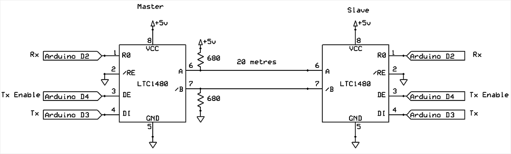
This page reports on some excellent work done by Nick Gammon on a similar idea, with a different hardware basis. He also supplies a circuit diagram for a simple ($6) interface, and example code using the library.
The rest of this page derives from Nick Gammon's page about interconnecting multiple Arduinos via an RS485 connection. There would be nothing to get in the way of connecting other devices to the "LAN", other than duplicating the software already implemented for the Arduino nodes.
So if Nick's page "has it all", why this page? Web sites come and go.
First, here's a second source for his RS-485 protocol library. That is a .zip file. Just unzip the contents into your Arduino "libraries" folder, and, as usual, restart the IDE. This copy may be out of date! You really ought to fetch the code from Nick's site... if it is available.
And here's a copy of Nick's circuit diagram, showing two nodes on the "LAN"...
For this... indeed for all parts of Nick's RS-485 work... there is more detail on his page.
Nick's library provides for....
The final design decision means that only 16 valid bytes- for- transmission arise. Each byte of data will be sent over the LAN as two bytes. The benefit of this cost is that we can check incoming bytes and be quite confident they weren't corrupted in transit if they seem to be okay. The values 0x02 and 0x03 are not among the valid "data" bytes, so you need not worry that a "data" 0x03 will be misunderstood as an "end packet" byte.
In addition to the data validation tools already discussed, a CRC (cyclic redundancy check) follows each packet. It guards against noise and the possibility that some bytes were somehow lost.
(Much... but not all... of the following is just copied directly from Nick's page. Good bits: "blame him". Bad bits: blame me!)
The library was written to allow for various hardware interfaces (e.g. software serial, hardware serial, I2C). Thus when using it you supply three "callback" functions which have the job of doing the actual sending/receiving.
To use the Arduino's D0/ D1 serial port, the callback functions might look like...
  void fWrite (const byte what)
    {
    Serial.write (what);
    }

  int fAvailable ()
    {
    return Serial.available ();
    }

  int fRead ()
    {
    return Serial.read ();
    }
For a dedicated serial port... good idea, if you don't have a Mega... you might use:
  #include <NewSoftSerial.h>

  NewSoftSerial rs485 (2, 3);  // receive pin, transmit pin

  void fWrite (const byte what)
    {
    rs485.print (what);
    }

  int fAvailable ()
    {
    return rs485.available ();
    }

  int fRead ()
    {
    return rs485.read ();
    }
Again... mostly just imported from Nick's page. The following sets up a "LAN" with a master and a slave. When you change the setting of a potentiometer connected to the master, the brightness of a light connected to the slave changes. "Instantly", by human perceptions.
It is your responsibility to turn on the "write enable" pin before and after doing a "send". This configures the RS485 chip to allow writing to the network. An example master is:
#include "WConstants.h"
#include "RS485_protocol.h"
#include <NewSoftSerial.h>

const byte ENABLE_PIN = 4;
const byte LED_PIN = 13;

NewSoftSerial rs485 (2, 3);  // receive pin, transmit pin

// callback routines

void fWrite (const byte what)
  {
  rs485.print (what);
  }

int fAvailable ()
  {
  return rs485.available ();
  }

int fRead ()
  {
  return rs485.read ();
  }

void setup()
{
  rs485.begin (28800);
  pinMode (ENABLE_PIN, OUTPUT);  // driver output enable
  pinMode (LED_PIN, OUTPUT);  // built-in LED
}  // end of setup

byte old_level = 0;

void loop()
{

  // read potentiometer
  byte level = analogRead (0) / 4;

  // no change? forget it
  if (level == old_level)
    return;

  // assemble message
  byte msg [] = {
     1,    // device 1
     2,    // turn light on
     level // to what level
  };

  // send to slave
  digitalWrite (ENABLE_PIN, HIGH);  // enable sending
  sendMsg (fWrite, msg, sizeof msg);
  digitalWrite (ENABLE_PIN, LOW);  // disable sending

  // receive response
  byte buf [10];
  byte received = recvMsg (fAvailable, fRead, buf, sizeof buf);

  digitalWrite (LED_PIN, received == 0);  // turn on LED if error

  // only send once per successful change
  if (received)
    old_level = level;

}  // end of loop
This example demonstrates how you might command a light in some other part of the house to dim up/down. It reads a potentiometer connected to pin A0 (with the other sides of the pot connected to +5V and Gnd). This gives an analog reading which is then sent to the slave.
We use a 3-byte message format:
Then we wait for a response from the slave to confirm it got the message. If not, we turn on an "error" LED.
The code for the slave could be:
#include "WConstants.h"
#include <NewSoftSerial.h>
#include "RS485_protocol.h"

NewSoftSerial rs485 (2, 3);  // receive pin, transmit pin
const byte ENABLE_PIN = 4;

void fWrite (const byte what)
  {
  rs485.print (what);
  }

int fAvailable ()
  {
  return rs485.available ();
  }

int fRead ()
  {
  return rs485.read ();
  }

void setup()
{
  rs485.begin (28800);
  pinMode (ENABLE_PIN, OUTPUT);  // driver output enable
}

void loop()
{
  byte buf [20];

  byte received = recvMsg (fAvailable, fRead, buf, sizeof (buf) - 1);

  if (received)
    {
    if (buf [0] != 1)
      return;  // not my device

    if (buf [1] != 2)
      return;  // unknown command

    byte msg [] = {
       0,  // device 0 (master)
       3,  // turn light on command received
    };

    delay (1);  // give the master a moment to prepare to receive
    digitalWrite (ENABLE_PIN, HIGH);  // enable sending
    sendMsg (fWrite, msg, sizeof msg);
    digitalWrite (ENABLE_PIN, LOW);  // disable sending

    analogWrite (11, buf [2]);  // set light level
   }  // end if something received

}  // end of loop
The slave simply loops looking for incoming data. The library returns a non-zero "received count" if a valid message is received. Then the slave checks the address (first byte of the message) to see if it is addressed to it (rather than a different slave). If not, it ignores the message.
Then if checks for a valid command (e.g. 2 = turn light on). If not, it ignores it.
Finally if it passes these checks, it sends back a response. A small delay (of 1 mS) is inserted to give the master time to prepare for a response. That way the master knows the slave is alive, and responding.
A small "gotcha" caught me when testing with hardware serial. The following code didn't work properly:
 digitalWrite (ENABLE_PIN, HIGH);  // enable sending
 sendMsg (fWrite, msg, sizeof msg);
 digitalWrite (ENABLE_PIN, LOW);  // disable sending
Whilst it worked fine with software serial, the code above "turns off" the RS485 chip too quickly, because the last byte is still being sent from the serial hardware port.
A couple of solutions worked:
 digitalWrite (ENABLE_PIN, HIGH);  // enable sending
 sendMsg (fWrite, msg, sizeof msg);
 delayMicroseconds (660);
 digitalWrite (ENABLE_PIN, LOW);  // disable sending
I'm not very happy with hard-coded delays. Too low and it is still too quick, too high and the slave is responding before you turn the transmitter off. The exact value has to be carefully tuned, and depends very much on the baud rate in use. The value required appears to be approximately two character times. So for 28800 baud, one character time is 1/2880 which is 347 uS. Doubling that gives about 690 uS.
Another approach is:
 digitalWrite (ENABLE_PIN, HIGH);  // enable sending
 sendMsg (fWrite, msg, sizeof msg);

 while (!(UCSR0A & (1 << UDRE0)))  // Wait for empty transmit buffer
     UCSR0A |= 1 << TXC0;  // mark transmission not complete
 while (!(UCSR0A & (1 << TXC0)));   // Wait for the transmission to complete

  digitalWrite (ENABLE_PIN, LOW);  // disable sending
This requires fiddling with hardware registers (and the exact ones depend on whether you are using Serial, Serial1, Serial2 and so on). The first loop waits for the hardware chip's buffer to empty, at the same time setting the "transmission not complete" flag. The second loop waits for the final byte to be clocked out by the hardware.
This setup seemed to work pretty well. Transmission was over ordinary "speaker cable". It wasn't twisted pair or shielded. At 28800 baud it took about 7 mS to send the command and receive a response.
There's some discussion of Nick's material at a discussion which ensued at the Arduino forum.
![]() Page tested for compliance with INDUSTRY (not MS-only) standards, using the free, publicly accessible validator at validator.w3.org
Page tested for compliance with INDUSTRY (not MS-only) standards, using the free, publicly accessible validator at validator.w3.org
CSS behind the page checked, at least once upon a time!, with http://jigsaw.w3.org/css-validator/
Why does this page cause a script to run? Because of the Google panels, and the code for the search button. Also, I have some of my pages' traffic monitored for me by eXTReMe tracker. They offer a free tracker. If you want to try one, check out their site. Why do I mention the script? Be sure you know all you need to about spyware.
....... P a g e . . . E n d s .....