This page is browser friendly, by the way. Make your browser's window less wide than your whole screen and you will find the narrower columns much easier to read. For more tips, see my Power Browsing hints.
This essay explores ideas for creating a simple, inexpensive LAN (local area network) over which the enthusiastic hobbyist could make devices like Arduinos and PCs communicate with one another.
There aren't any "new" ideas here... but maybe you won't have come across them explained at this level.
After I had written this, a discussion ensued at the Arduino forum. In that, an alternative hardware layer was explained, using RS485 transceiver chips.
Following the discussion, the primary contributor wrote up what "we" had "discovered" in an introduction to using RS-485, which I commend to you. He not only discusses the hardware issues but also provides a useful Arduino library with routines for sending error-checked packets over the LAN. If that page is somehow not available, I have done a clone of the information about RS-485, the error resistant inter-device transmission library, and the Arduino for you.
What does the page you are reading hold? While it is a candle as opposed to the halogen lamp of the material just cited, if you are new to the ideas of building "home-brew" LANs, you might find that what follows helps you get going....
I will first describe the underlying electronics and wiring. Then I will go into the design of things to be connected over such a LAN.
Once the hardware is in place, what you can do with the LAN only depends on how hard you want to work on the software side.
It would be quite easy to set up a weather monitoring system, or a burglar/fire alarm system... or a hybrid system with features of both!... with one PC on the LAN, and multiple small sensors which would "report in" to the PC, which could record the weather data, or take action dictated by the alarm system inputs. You could even have attached devices which would respond to commands from the PC, e.g. "close the curtains".
The "attached devices" could be further PCs for demanding job, or microprocessors like the Arduino, which are remarkably capable. I regularly use the RBBB Arduino clone from ModernDevice, which costs $12 as an easily assembled kit. (No SMT components). (You only need a PSU in addition to the RBBB.)
With more work on the software, the LAN I propose here could be set up as a peer-to-peer system, with the equivalent of file sharing, etc.
The LAN I propose here is partly inspired by a system used for many years, certainly into the 1980s (perhaps to this day, but I don't know) to connect fire department call boxes across a town to the headquarters, so range will not be a problem.
Only two conductors are needed... simple bell wire will do to run one of these LANs around a house, so wiring expense will not be a problem.
I believe the system could be extended to allow wireless links between sub-LANS.... but I haven't thought that one through yet, so if you want wireless links, put on your thinking cap.
But.
Yes, there's always a but.
To get those advantages, you have to give up speed. The LAN will not be capable of high data rates. That's not to say it won't be able to manage, say, 100 characters a minute, but don't expect it to carry live video!
We'll start on what the hardware requirements are in a moment... but first we need a name.
The fire department's system worked by "breaking" a wire to send messages. In a play on "break dance", for no particular reason other than it having a nice ring to it(?) I think I'll call my LAN system "BreakWire" (Google that!)
The hardware....
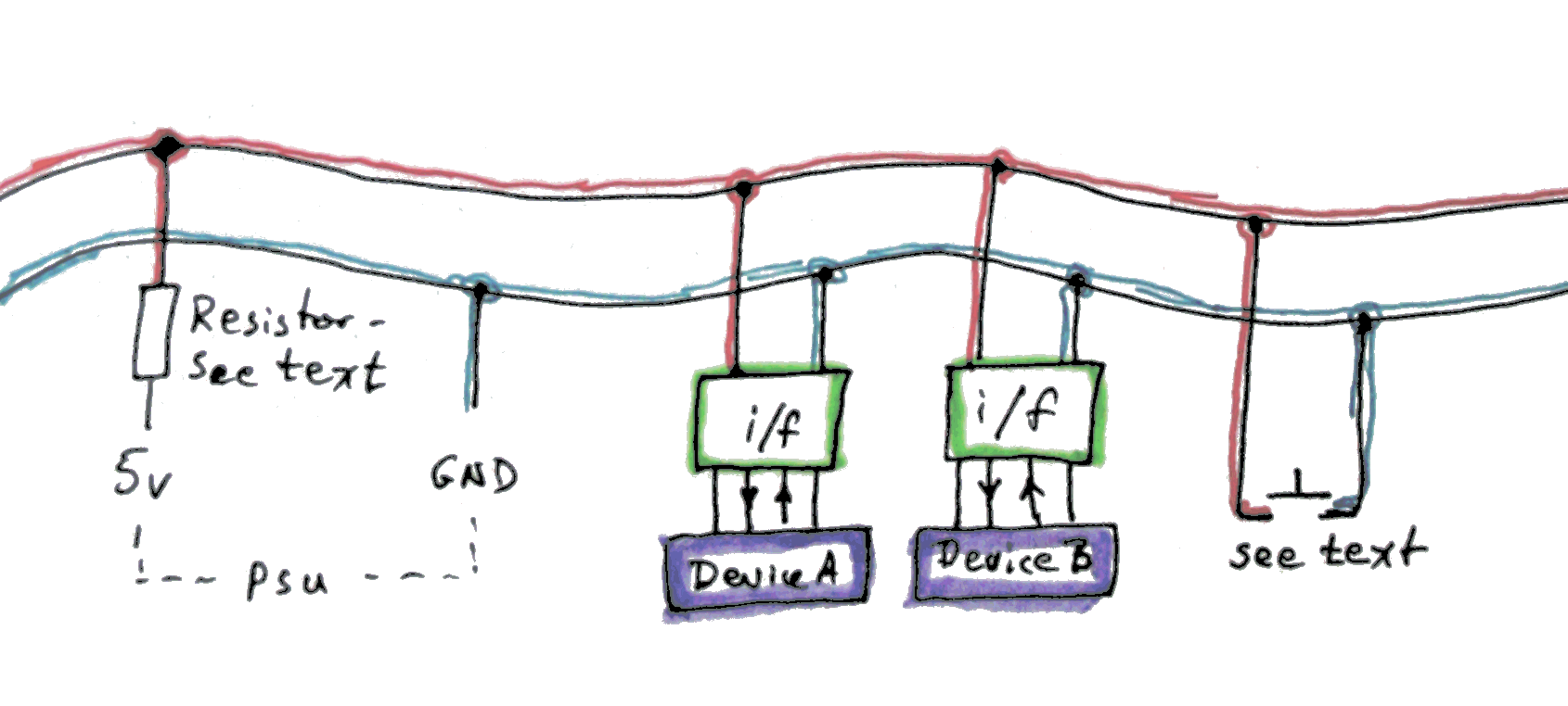
As I said, just two wires would run from place to place to place to create the LAN. "Across" them, at one point at least, a voltage would be applied... but through a large resistor. We'll discuss its role in a moment.
For as many devices as you wanted on the LAN, you would attach simple interfaces. Two are shown on the diagram, labeled "i/f". They would have one input and one output, and the device you wanted to connect to the LAN would connect to these. (You wouldn't in every case need both, but you would usually want both.)
We'll come back to look at the details of the interface later.
At the right hand end of the diagram you'll see a simple momentary switch. This would not normally be present on a BreakWire LAN, but it is on the diagram to help me explain to you how the BreakWire LAN works.
This brings us back to the resistor between the voltage source and the top LAN wire.
If you were to press the switch, it would short the two wires together. With a suitable resistor, this would cause the source of the voltage no problem.
For the moment, assume that the interfaces place no load on the voltage in the BreakWire LAN wires.
If you put a voltmeter across the two wires of the BreakWire LAN, it would read nearly 5 volts. When the push button is pressed, the voltmeter would read nearly zero volts. (The "nearly" won't be an issue, if we are careful, but the longer the BreakWire LAN, the greater the "error" will be.)
Now we return to consider the interfaces more closely.
In each, there is a device called an "opto isolator". One half of that is a resistor and LED. That half connects to the BreakWire LAN wires as shown....
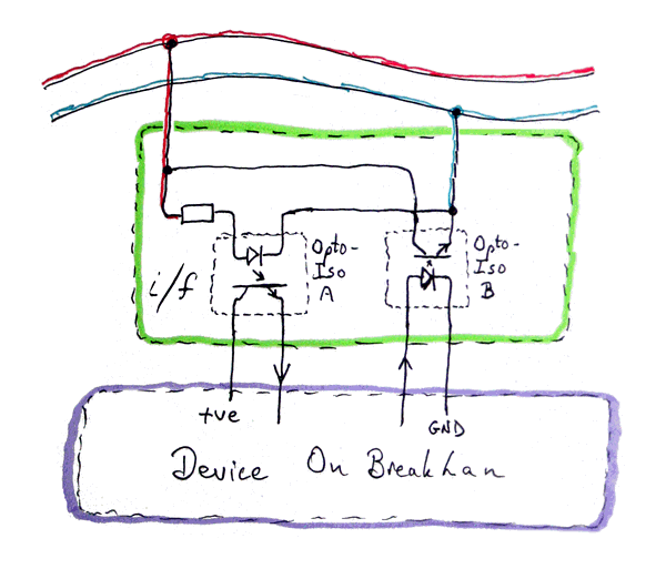
... and as long as we are careful to match the device supplying the voltage to the BreakWire LAN to the number of interfaces we want to attach, then the LED will normally be on.
You can't see the LED. It is inside the opto-isolator. And it shines on a photo-transistor. The LED / opto-isolator I'm speaking of is what is inside the box marked "Opto-Iso A" in the interface diagram above. The photo-transistor acts as a switch, and with just a little bit of knowledge, you can easily drive an input of the attached device from the photo-transistor.
That's how the attached device will "know" what the voltage is in the BreakWire LAN wires.
The secret of the BreakWire LAN is this:
All of the attached devices will watch the voltage in the wires, which we will call the signal level from now on. Normally, when all is "quiet, it will be high. From time to time, "things" (which we are about to go into) will happen to make the signal level go low.
We won't be using Morse code, but I am going to speak for moment as if we were.
Suppose one of the attached devices was equipped with a room fan it could turn on and off. Further suppose the device has been programmed so that if the Morse for "GO" is "tapped out" with the signal level, then the device will turn the fan on, and if the Morse for "STOP" is tapped out, the fan is turned off.
This is the central idea of BreakWire. The rest is details!... which I will now go into.
How does the signal level get pulled down? Remember the simple mechanical switch? We are replicating that switch with the second opto-isolator in the interface, the one labeled "Opto-Iso B". We will have to be careful to use a suitable supply of 5v (and associated resistor) to BreakWire LAN's positive wire, so that we do not exceed the current carrying capacity of the transistor in opto-isolator when it is shorting the BreakWire LAN wires. (The calculations are not complex... we just have to remember to do them!)
Continuing with "how does the signal level get pulled down": If the output from the connected device is switched high, the LED in Opto-Iso B will go on, the photo-transistor "switch" will start conducting, and the wires of the BreakWire LAN will be shorted. And every other device on the BreakWire LAN will "see" that they are shorted. Bingo! We have "communication" across the LAN!
What is wrong with this picture?
Why is that not the whole story?
There's nothing "wrong" in what I've said so far... but I haven't said enough. There is "one little problem" to be dealt with. See what it is?
What happens if two devices try to "talk" at once? I.e., continuing with our initial simplification that says messages will be sent via Morse code, what happens if, say, Device A is sending "SOS" and Device B is sending "Quick Brown Fox"?
I'm afraid that what happens is that the pattern of high and low voltages on the BreakWire LAN is just a meaningless jumble.
We will solve the problem in different ways depending on the system we are building.
In most schemes you will want to give each device on the LAN a unique identifier. This alone could be the subject of pages of proposals and discussion. For now, we will content ourselves with setting up something which limits us to 256 devices on any given BreakWire LAN. The device ID will be determined either with jumpers, with hard-coding in the software, or by a combination. The allocation of numbers to devices will be handled by a human, "by hand".... rather like assigning fixed (local) IP addresses on a TCP/IP LAN, eschewing a DCHP service.
One approach to solving the "two or more people talking at once" problem is to appoint a "master" device which will be "chairperson of the meeting." That device can "talk" when it wishes to, and it can issue commands such as "Device X, you have permission to speak for the next 2 seconds, during which I will be listening for an answer from you." Device X could be, for instance, an Arduino monitoring barometric pressure, and it might be programmed to respond with the latest reading whenever it is "invited" to "speak".
Another system is a little more complex, but it has the advantage of avoiding the need for a master.
It works best on a LAN that doesn't have a lot of traffic.
Under that system, anyone can "speak" at any time. At any moment, a device may say "Hey, Device xxx here!" While it is "saying" that, it also watches the BreakWire LAN line. If no one else is trying to speak at the same time, the message should have appeared on the line, un-corrupted. If it did not then Device xxx assumes someone else was trying to speak at the same time as Device xxx was trying. The other device will have had the same experience. This is called a "collision". Both devices would then shut up, and wait a bit before trying again. The "a bit" would depend on the device's number. Thus, they should not both try again at the same time.
Before speaking, every device listens to see if some other device has just said "Hey...", and waits if it has. If a device says "Hey..." successfully, it gets a little window of time during which no other device should be trying to send something onto the BreakWire LAN. The protocol can be simple or complex.
With a simple protocol, the time slot won by a successful "Hey..." is of a fixed length, and the time slot winner must finish sending before that time is up.
Under a more complex protocol, you could have rules that say after winning a time slot, a device will always have time for a command which says "I am claiming sole use of the BreakWire LAN for yyy seconds."
Those, of course, do not set out all the necessary details... They are only meant to hint at the possibilities.
Not Morse.
Of course, the messages won't be sent in Morse code.
The basic unit of all messages will be the ordinary byte (8 bits, or "binary digits", i.e. 1s and 0s.)
The data will be sent by ordinary serial data protocols, no wheels need be re-invented there.
It will be up to system designers to decide what basic serial data rules and packet rules they want to specify for their systems... The basic BreakWire LAN design doesn't force uniformity in any of these areas. Of course, if certain common ground can be agreed, collaborative work will happen more readily... but those are stories for other days.
While the theory set out above is neat, tidy, and simple enough, the real world is messy, untidy and complex.
In early work with BreakWire LANs, it will behoove the experimenter to realize that the behavior of the signal will not be quite what one would hope. The transition from (near) zero volts to (near) 5 volts will not be instantaneous, nor will it even necessarily be "reliable". When the signal is made to change, it probably will change... eventually. Designing the system to use a quite slow data rate will allow you to "look" at signals in "the middle" of 1s and 0s in the data stream, at points in time well away from the (stretched) moments where the levels may be changing, and (perhaps) not doing so "cleanly".
So! Where to start?
I would start with three interfaces, driven by three Arduinos.
The first Arduino will be programmed to send numbers out onto the BreakWire LAN. The other two Arduinos would, initially, only be expected to watch the BreakWire LAN, and somehow display any numbers they saw being sent on the BreakWire LAN.
From there, I would proceed to having the first Arduino send 123 from time to time, and 231 from time to time.
In each case, it would pause for a bit after sending one of those numbers.
One of the other Arduinos would respond any time it saw a 123 on the BreakWire LAN, the other, obviously, would be programmed to respond when it saw a 231.
"Respond how?" I hear you ask.
It could... probably should, initially... be something really simple. You could have a few push buttons on each of the responding Arduinos, and the response would report which buttons were pressed at the moment.
All rather pointless? In itself, if you take it no further, perhaps. But if you did the work to get a system working that far, you would have solved a whole bunch of problems and opened the path to some fun and not-pointless exercises.
There's a possible problem scenario in even that very, very simple system.
You would have to ensure that neither of the responding Arduinos could ever respond with a 123 nor a 231.
Easy to arrange, of course.
You had spotted the need to arrange that, hadn't you? And you do understand why arranging it is important?
I hope the above inspires someone to take this on. I wish I had time to "play" with actually doing it myself!
For early work, if you are using Arduinos, just use NewSoftSerial to handle conversion of bytes to and from 1s and 0s, and connect the interface to two digital I/O lines of your choice, e.g. D2 and D3, and tell NewSoftSerial to send and receive via those pins.
![]() Page tested for compliance with INDUSTRY (not MS-only) standards, using the free, publicly accessible validator at validator.w3.org
Page tested for compliance with INDUSTRY (not MS-only) standards, using the free, publicly accessible validator at validator.w3.org
CSS behind the page checked, at least once upon a time!, with http://jigsaw.w3.org/css-validator/
Why does this page cause a script to run? Because of the Google panels, and the code for the search button. Also, I have some of my pages' traffic monitored for me by eXTReMe tracker. They offer a free tracker. If you want to try one, check out their site. Why do I mention the script? Be sure you know all you need to about spyware.
....... P a g e . . . E n d s .....