(If you already know you want my printed circuit breakout for eight pin ATtinys, PCB271, bare board... or the kit to make a Morse Code Reader... you can just skip to the "ordering and assembly" details page.)
A quick aside, before I start: There's a fun site to convert text to "Morse" and vice versa. (Enter ... --- ... to play with that... use periods (full stops), hyphens and spaces.)
------------
For very little expense, you can do something much more fun. Imagine a small gizmo with some sort of "doorbell" (momentary) switch, which could "translate" Morse code, as input via the switch, into ordinary characters, and display them on a screen. You tap "dit-dit-dit dah-dah-dah dit-dit-dit... and "SOS" appears on the display!
No need to imagine. Buy the kit; assemble one!
This page will give you an overview of PCB271, my Morse Code Reader. The software, the big ingredient, was by Edgar Bonet.
Besides being nice for what it does, it is intended as an example of what can be done with the wonderful little ATtiny chips.
If you can do Arduino, you can do ATtiny. (They're actually easier, on the hardware side. And less expensive! Well... easier, if you are already set up to "do Arduino".)
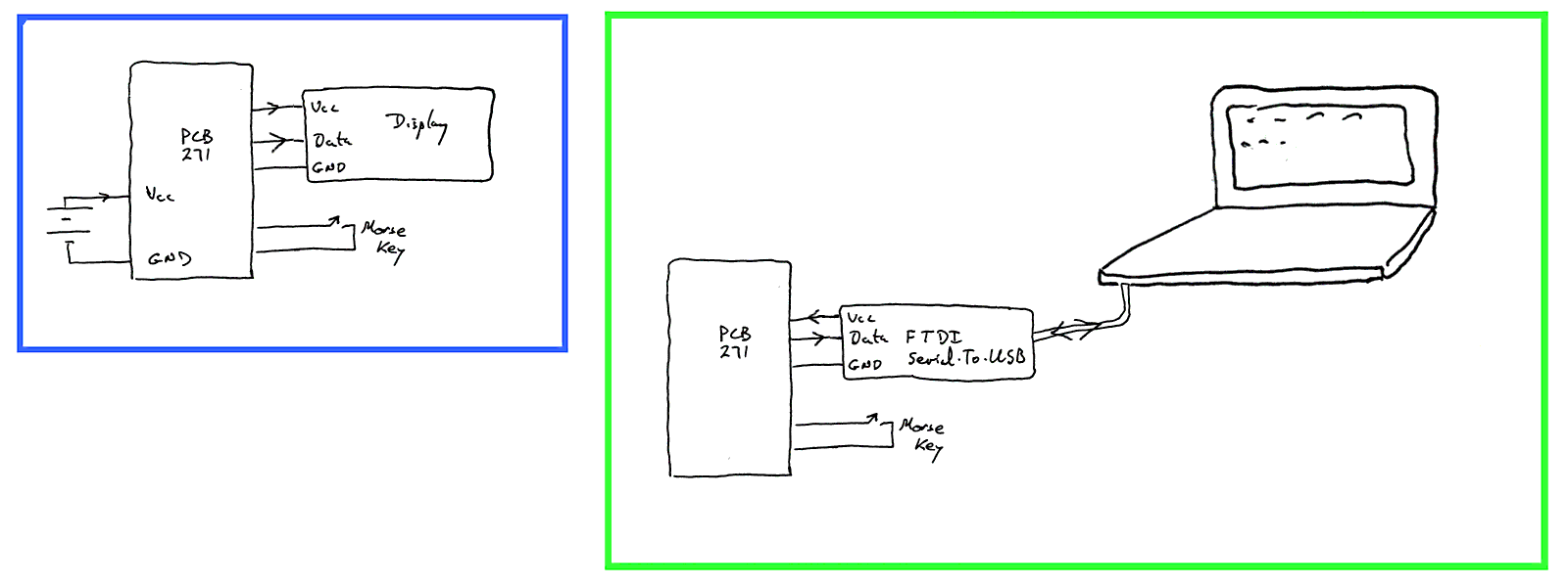
Here are two ways set the Morse Code Reader...
----- First alternative...
On the left, inside the blue box...
Obviously nice, as it doesn't depend on so much external "stuff". And, depending on the power, it is portable.
But you have to buy a little serially driven display. DETAILS TO COME... complain if you see DETAILS.... And you have to provide power. (A USB cable to a charger or port works well, if the display doesn't demand too much current.)
----- Other alternative...
On the right, inside the green box...
Also nice, as it involves fewer connections. And although the diagram looks "messy"... it only needs things you probably already have! The "FTDI interface" is just the device you use to program Arduinos like the Arduino Pro Mini... the inexpensive ones, which don't have serial-to-USB circuitry on their PCB. (Makes sense to me... pay for a not very expensive cable once, instead of buying the circuitry again and again with each Arduino!) (Further details below.)
The thing to the right of the FTDI is supposed to be whatever computer you use to program your Arduinos.
To watch the output from the Morse Reader, just connect an FTDI cable, open the Arduino IDE, and start the Arduino Serial Monitor. That's it. You'll be all set (You don't need to compile or upload anything.)
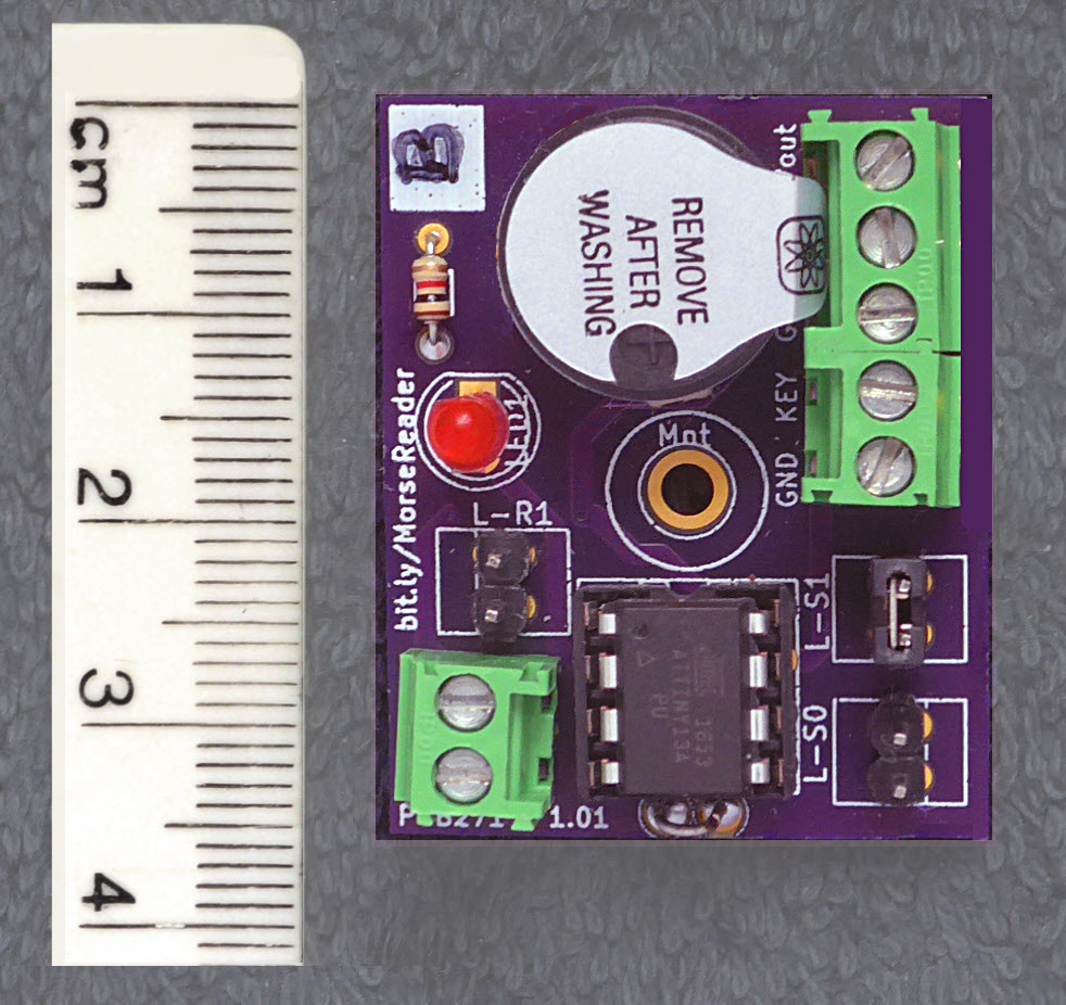
The "clever bit" of the Morse Reader is the software. But once you have a programmed ATtiny85, which I can sometimes supply, you also need to hook it up to things. That's where PCB271 comes in.
What I've shown as "PCB271" in the diagrams amounts to almost nothing! It is just the small PCB shown (with components soldered in) in the illustration at the top of the page.
It is what is on offer, as a bare PCB, or in a kit with parts for the Morse Reader. (Ordering details are on the Ordering and Assembly page.)
As I tried to indicate nearer the top of the page, the board can be set up in at least two ways.
----- Computer-less setup ("Computer-less" apart from the ATtiny, of course!)....
For the "computer-less" setup, you need a serially driven display (9600 baud).
LCD displays are easy. The only other things needed are a Morse key and a source of 5v or so. I use a USB port from my computer, or USB charger. Depending on your taste for buying new batteries and the demands of your LCD panel, it could also probably be run from batteries. Suitable LCD panels can be found on eBay, but for a reliable, dependable source, for which I for one am happy to pay a premium: Sparkfun (16x2, 5v) $25 + p&p at 4/18) (3v3 version avail, too), or take something like the once-available, wonderful Hobbytronics serial backpack £6 + p&p at 4/18) and marry it to one of their LCD panels spec'd for the widely used Hitachi HD44780 interface. (They had an 8x2 Character LCD, backlit, panel for £7.20 + p&p at 4/18)
----- Alternative setup....
Alternatively, you can use the Morse Reader connected to a "big computer" with the Arduino IDE installed. You need a "smart" programming cable, i.e. one of the ones with a USB/Serial adapter. The one you need, say, for Arduino Pro Minis. (FTDI being the commonly used one). (That is "the way to go, I think, if you want to go far with Arduinos... why pay for the programming interface over and over again?) ($15-$20, if you are lazy/ cautious, and go the Sparkfun route.)
If you "go" this second route, you connect just 3 wires from the Arduino programming device to PCB271-MorseReader. In this setup, the Morse Reader takes its power from the big computer, and the Reader's output appears on the Arduino IDE Serial Monitor. (No Arduino (other than the already programmed ATtiny) needs to be present! The Arduino IDE will work fine, anyway.)
At "Pie1", you connect a self-oscillating piezo sounder. (It is "optional"... it merely tells you when the key is depressed, but the aural feedback will be a big help if your are trying to learn the code.) Note: These are polarized devices. It matters "which way 'round" you connect them. RapidOnline.com has a suitable device. Be careful that the one you use doesn't demand more current than the ATtiny can supply.

On the left: The overall circuit for the Morse Reader.
Besides what you can glean from here, I commend Edgar Bonet's excellent page on his ATtiny Morse Reader to you. There is a a competition for any Arduino programmers wanting to try making a similar Morse Reading device. (The prize money is currently not won... but check with the main page of the competition to see if that comment is up to date before starting an entry! (Please cite this page's URL (http://sheepdogguides.com/elec/pcb/PCB271-ATtiny Morse brd1.htm) if writing to tell me this comment is out of date.) There's more on the Bonet Morse Reader (PCB271) in both of those places.
There are two "links" to make or not make. They control the speed you need to send the Morse at, if the Morse Reader is to successfully decode what you send. If neither link is "made", the Reader expects the Morse to be sent slowly. When it starts up, it "sends" an "R" (dot- dash- dot) to the piezo buzzer, to show you the speed it expects.
The following is a general summary of what you need for PCB271, Morse Reader. See my Ordering and Assembling PCB271 page for a full list and more details.
U1    ATtiny 85, with Edgar Bonet's
        Morse Reader code in it.
Pie1  Self oscillating piezo sounder.
        Suitable: Rapid Online part 51-76700
Links 3 pairs of pins, 0.1" apart... for doing
        a reset, or for selecting the speed that
        the Morse Reader is looking for
Screw Terminals... 1x two way, 1 x five way...
        if you want to be "posh". You could, of
        course just solder flying leads to the
        pads provided. Pads 0.15" apart, if you
        want to fit screw terminals
LED and Resistor: Directly driven by a pin
        of the ATtiny... don't demand too much
        current. Resistor pads suitable for
        a 1/8 W resistor
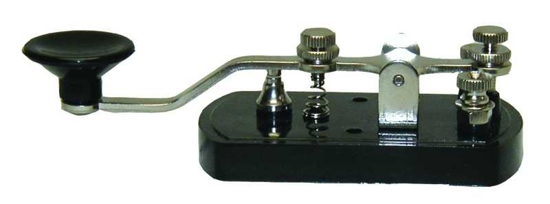
You can send Morse to the Reader just by tapping two wires together... but wouldn't proper key be nicer?...
That's it, I hope!
Please spread the word?? If you think others would find this page interesting, "http://bit.ly/MorseReader" is a quick way to get to a starting point!
Click here to visit editor's Sheepdog Software (tm) freeware, shareware pages.
Click here to visit the homepage of my biggest site.
Click here to visit the homepage of Sheepdogsoftware.co.uk. Apologies if the "?PCB271-brd1" I added to that link causes your browser problems. Please let me know, if so?
To email this page's editor, Tom Boyd.... Editor's email address. Suggestions welcomed! Please cite "PCB271-ATtiny Morse brd1.htm"
![]() Page has been tested for compliance with INDUSTRY (not MS-only) standards, using the free, publicly accessible validator at validator.w3.org. Mostly passes... but scraps of v4 or earlierPC_B271-ATtiny Morse brd1.htm HTML presist, should be tidied.
Page has been tested for compliance with INDUSTRY (not MS-only) standards, using the free, publicly accessible validator at validator.w3.org. Mostly passes... but scraps of v4 or earlierPC_B271-ATtiny Morse brd1.htm HTML presist, should be tidied.
AND passes...

....... P a g e . . . E n d s .....