 Bookmark this on Delicious
 Recommend to StumbleUpon
There's a neat device called an optocoupler. In an ironic twist, the same device is also called an optoisolator. I prefer the second name, because it stresses what I find valuable about the device. But Google Trends tells me that "optocoupler" is what most people call it.
Whatever you call it, it is a useful device. It let's you "connect" two signals (couple them), while leaving them isolated from each other, which can be good for various reasons.
The basic idea of the device is cute: Inside the little blob of plastic with legs on it is an LED and a light sensor. You feed the signal in on the LED, the light jumps across the "little cave" inside the blob of plastic, and the light sensor acts like a switch, turning the isolated output "on" and "off". (If you are new to them, I've done an introduction to optocouplers for you.)
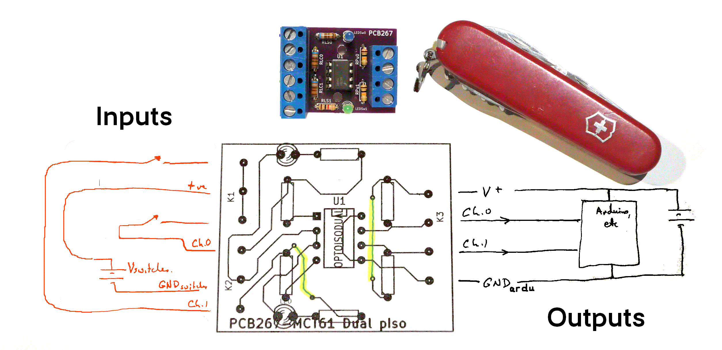
A "by hand" prototype and the first batch of professionally manufactured boards from the excellent OSH Park work just fine. (The board will eventually be made a "public project", which you will be able to order directly from OSH Park, if you wish. For the moment, while some final tweaks are completed, the project is not public, so that I can aviod having multiple versions of the board "out there" to cause confusion! If you want a copy Right Now, email me.)
However, with artwork to discuss the early versions nearly finished, I realized I could swap some terminals around to make the device more user friendly. (In early versions, you connected the power for the inputs, for the optocoupler's LEDs side "upside down", with the Ground connection above the +ve connection.)
No change in the circuits will be needed, but the layout of the PCB will need tweaking. So we're in a minor hold. Sorry. As I say... underlying schematic tested and proved okay. Working on the PCB re-routing. "Shouldn't" be a big deal. Everything here has been tweaked as if the new design were already a reality... but I have to confess that it is all the result of photo manipulation software so far, based on "real" circuits etc. The change is so trivial that the upper side of the board will look no different.
I seem to have written this up twice. Sigh. Alternative documentation for PCB267- dual opto coupler
The diagram above shows you half of what is present in the breakout board. There are two of everything you see, apart from the V (voltage/ power) connections and the ground connections.
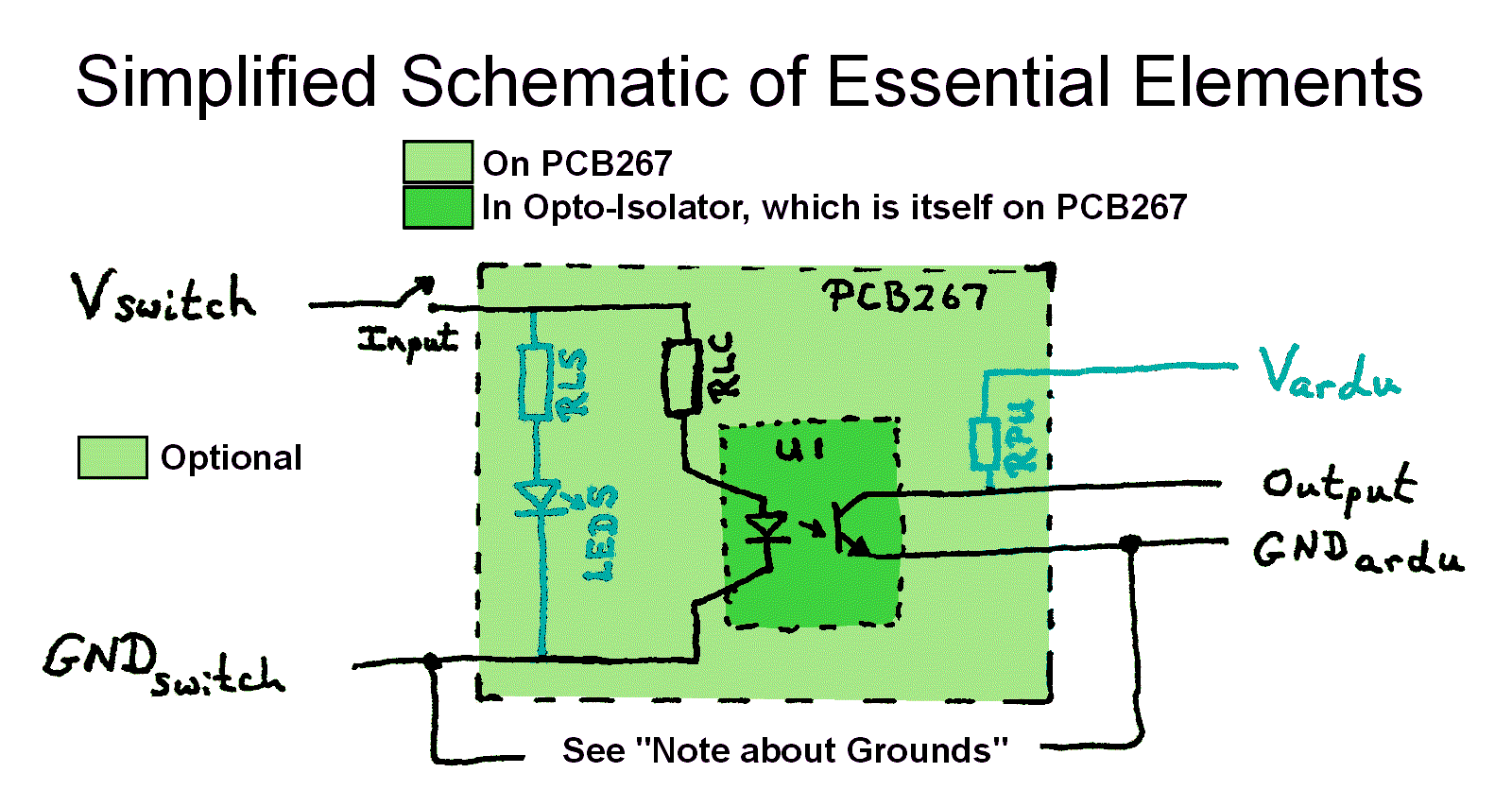
If a voltage is applied to one of the inputs of PCB267, the optional discrete LED designated "LEDS", if fitted, lights up. ("LED on input Signal". As with most elements of the circuit, there are two of them on the breakout board, designated LEDS0 and LEDS1.)
When s voltage appears at the input, the LED inside the optocoupler (U1) also comes on. That causes the photo-transistor inside the optocoupler to conduct.
While the photo-transistor is conducting, "Output" will "be connected" to GNDardu.
"Note About Grounds": Ordinarily all the "grounds" in a circuit are connected together. In your use of PCB267, I cannot think of a time when you would want to connect GNDswitch with GNDardu. (Connecting them would degrade the isolation that is often the reason for using an optocoupler.
If the optional resistor RPU ("Resistor- Pull Up") is fitted, and the optional voltage Vardu (Volts from ARDUino) is supplied, then the output will be pulled up to (near) Vardu when the LED inside the optocoupler (U1) is NOT being illuminated by the LED inside U1.
The external circuits on the right can, of course, be something other than an Arduino. Forgive my partisanship?
Mostly clear, I hope, to those who know a bit about optocouplers. I will explain again in more detail, later, so don't despair if my diagram is NOT clear.
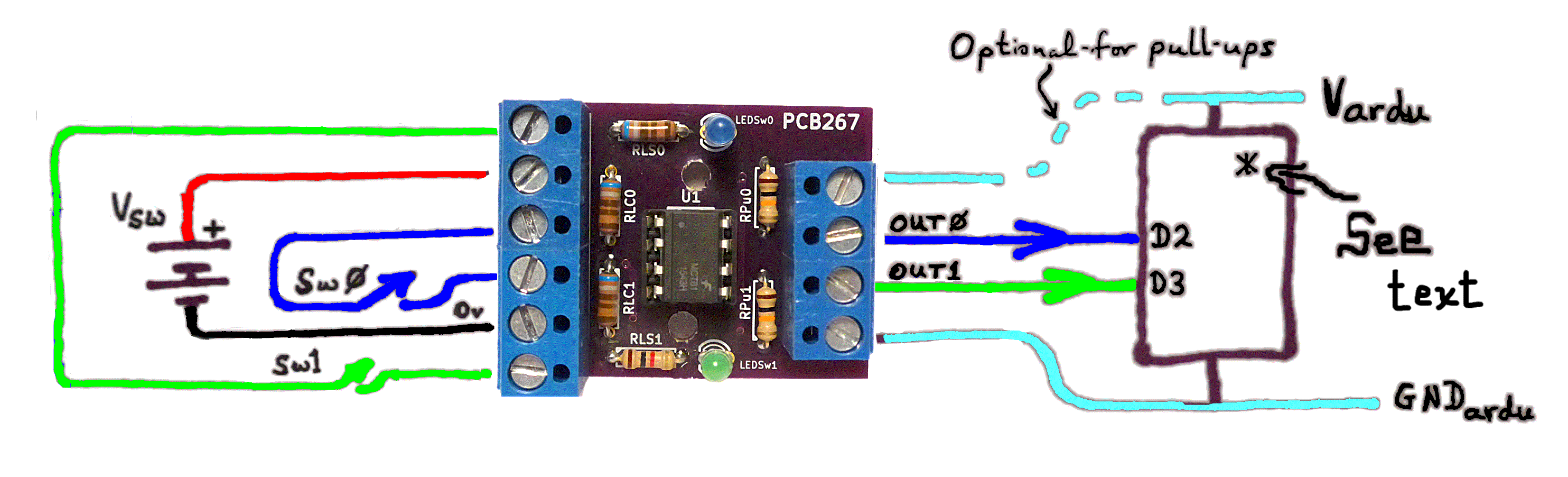
On the right: The rectangle marked "See Text". What follows is that text!...
The rectangle, etc, stands for whatever you want the signals from Sw0 and Sw1 passed on to. There are limits to what the outputs of PCB267 can drive, of course... but they can, for instance, drive an input to an Arduino, a Pi, etc. Or they can drive the base of a transistor.
I used "D2" and "D3" to suggest pins on an Arduino. (You don't have to use D2 and D3!) Reminder for Arduino novices: be sure, as ever, that if you connect an output from elsewhere, e.g. PCB267, to a pin of an Arduino that you have set that pin to an appropriate pin mode. For what comes from PCB267, connected to D2, you would want pinMode(2,INPUT), or pinMode(2,INPUT_PULLUP).
-----------
I have shown the power connections (Vardu and GNDardu) to the right hand (output) side of PCB267 in cyan to emphasis that they will normally be kept entirely separate from the power connections to the input side of PCB267. I.e. GNDsw (simply marked "0v" on the diagram, the "negative" "side" of the battery) would NOT be connected to GNDardu. (It could be, if necessary. But usually, you wouldn't connect these two grounds, contrary to the usual treatment of ground rails.)
The upper connection on the right is optional, in any case. (The connection from Vardu to PCB267.) You only need it if you want to use the optional pull-up resistors (on PCB267) on the two output-from-PCB267 lines. (There's no harm in the resistors being present even when you are not supplying a Vardu.)
The diagram to the right shows what's connected, as part of PCB267, to the four terminals on the right hand side of PCB267.
The two resistors are shown dotted because they are optional. If you leave them out, you would also leave out the connection to an external voltage. (It would connect through the top terminal, right hand side of board.) That voltage is just to pull up the outputs, through the resistors. (Of course, you can only leave them out if your external circuits are okay with a floating line on their inputs. If you are using an Arduino, if you use pinMode(x,INPUT_PULLUP), you don't need the pullups. ("INPUT_PULLUP" replaces the trick from the old days of writing to the input to "connect" the optional pullups present in Atmega (and other?) chips.) (There's more on all this stuff about pull-up resistors on inputs at my introduction to Arduino inputs. (It is as relevant to Pi electronics, but I don't know that the Pi has the internal optional resistors Atmel Arduinos have.)
Please be advised that PCB267 is not designed to handle "household" voltages. In any case, any use of it is at your own risk entirely.
Once everything is hooked up, here is how PCB267 should behave. The "switches" in the following are "virtual". The two inside PCB267 are certainly not switches. They represent electronics which act like a switch. In particular, remember that those electronics are quite limited in respect of how much current they can take before being damaged.
Let's assume you put a blue LED on Sw0. (As in the illustration above). That LED should be ON if the switch is CLOSED. When the LED is ON, Out0 will "look" as if the "virtual switch" inside the optocoupler is CLOSED, in other words, the voltage on it will be zero, as long as, because of resistance in your external circuits, the current flowing will be low.
If Sw0 is OPEN, the discrete LED should be OFF, and Out0 will either be "floating", or "showing" 5v, if you have fitted the pull-up resistor provided for on PCB267 (cite by ref), and supplied a voltage via the top terminal on the "outputs" side of PCB267. Again- all of the above only "works" if your external circuits have sufficient resistance to keep the current flowing low.
You might feel that the operation of the circuit is not intuitive, that the signal is being inverted as it passes through. Sparkfun offer a breakout board for an optocoupler which has some extra transistors to "invert the inversion", bringing it back to something that might be considered more intuitive... at the price of something else to go wrong. (The Sparkfun board does not have the discrete LEDs which show you the state of the input lines, either.)
Since you're still reading, the above must have been of some interest.
Anyone wanting to use PCB267 has some choices to make. I'll try to take you through them in order, and I will try to include all of the "answers" I used, with the boards I already have in use.
First: What will Vswitch be? I'm using 12v. I wanted to "see" closures on some switches on the roof of a building from a comfortable room in the basement. I wanted "strong" enough signals to "push through" the long wires. You can, as it happens, use DC or AC on the input side, if you take a few steps that I haven't yet written up here. For now, I am talking a DC Vswitch. (Vardu will also be DC.)
Once you have chosen Vswitch, you need to think about what Vardu is relevant to your wants. If you are using an Arduino, some people work with 5V Arduinos, others use 3V3 Arduinos. (Either works fine with PCB267.)
Now we come to a minor quandary, a place where a compromise must be made.
How much current to you want flowing through the external switches on the input side? Too low, and your signal risks being corrupted by noise from induced currents. Too high, and you'll need a "fancy" optocoupler. I've misplaced the bit of paper concerned, but I think I have about 10mA flowing through the LED inside my optocoupler. For whatever I have flowing, an MCT61 is one (of probably many) which will operate happily. I used 6k8 resistors for RLC0, RLC1 (Resistor-for Led in optocoupler Chip).
The other issues that must be considered when choosing your optocoupler are the voltage and current you want going through the photo-transistors on the output side. Because I intended driving an Arduino with the outputs, neither were problematic. I used 10K resistors for RPU (Resistor-Pull Up), and they would be fine for either Vardu. And the MCT61 would not break a sweat handing the power (combination of voltage and current) involved.
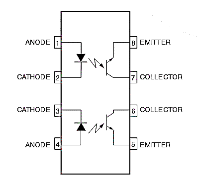
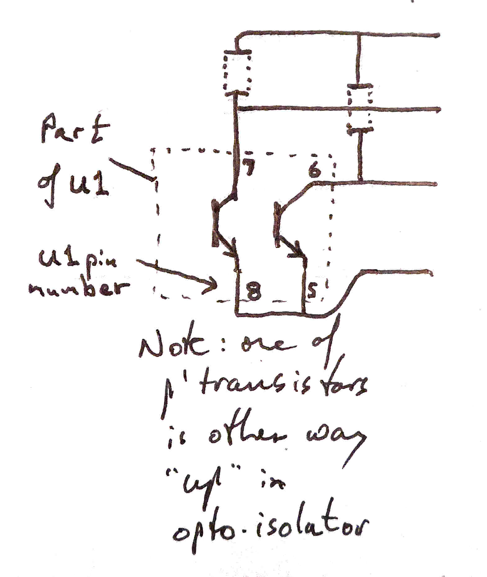
Other than the power limits, your choice of optocoupler is restricted to those with the same configuration as an MCT61. (Some optocouplers have both LEDs and/or both photo-transistors "the same way up").
Now we can deal with the discrete LEDs and their resistors. They are not "necessary"... but for the pennies they will cost, and the fact that they "cost" virtually nothing in other ways, you might as well include them on your PCB267. The one time you might want to skip them would be if Vswitch is provided by a battery.
The LEDs show you whether the inputs to PCB267 are high or not.
They have no effect on the current flowing through the LEDs inside the optocoupler.
Because you can choose (almost) any voltage for Vswitch, and you can choose any LED, and you can choose (almost) any brightness for the LEDs, I can't tell you what value the resistors (RLS0 and RLS1, Resistor- Led on Signal coming into PCB267).
With my Vswitch of 12 volts, and two pretty ordinary little LEDs, running not as brightly as they could, I found 6k8 for the blue LED and 1k for the green LED worked well. (I did it mostly by trial and error, starting with a "too high" resistor. (If you hook the LED to 12v with a too small resistor, you can fry the LED.) If you want to "do the sums properly", I have a guide to choosing resistors for LEDs.
Just in case you aren't clear: The current drawn from Vswitch will be the sum of the current flowing through the discrete LED(s) plus the current flowing through the LED(s) inside the optocoupler. Be sure that your source of Vswitch can handle the current that your choices could lead to.
I would recommend using LEDs of different colors, let's say blue and green. Remember that not all LEDs are created equal, and that if you want the brightness and current flow through each of them (and the associated LED inside the optocoupler) to be the same, the resistor values may have to be different from one another
Having chosen your LED colors, it would make sense to use the same colors for the related wires leading the two signals into PCB267, and the wires leading the derived outputs from PCB267 to the whatever inputs they drive, elsewhere.
Be careful if creating the six way terminal strip block with two 3-way strips. They usually have some mechanical "interlock" system to ensure a good result when used thus... but if you rush ahead, solder in a strip of three and then look at how the interlock system works, you may by then have painted yourself into a corner.
You are responsible for any consequences of using what is on any of my pages!
Please get in touch if you discover any flaws in the board, or any ways to go wrong. How are using it would also be of interest.
I would welcome news of any use you put the PCB to... especially if it comes with a photo, and permission to mention here. By all means give me with that any website, blog, etc, you want publicity for.
If you found this of interest, please mention in fora, give it a Facebook "like", Google "Plus", or whatever. I've almost given up writing these pages, because it seems they are seldom read, and of course not every reader will use them... so... is there any point? If you want more of this stuff, help!?
Click here to visit my main homepage where you
can explore other areas, such as education, programming, investing.
![]() Page tested for compliance with INDUSTRY (not MS-only) standards, using the free, publicly accessible validator at validator.w3.org. Mostly passes. A few "bad attributes" due to Google+ button, etc.
Page tested for compliance with INDUSTRY (not MS-only) standards, using the free, publicly accessible validator at validator.w3.org. Mostly passes. A few "bad attributes" due to Google+ button, etc.
....... P a g e . . . E n d s .....