(Filename: ATtiny-breakout-PCB271.htm)
I sell a small PCB for the ATtiny 85. (And similar 8 pin ATtiny's, too, of course.) (About $3)
I created it with a specific project in mind, and then realized that it makes a fairly convenient breakout board for many eight pin ATtiny projects.
If you want a copy of the board, go to the page about getting parts for PCB271-Morse Decoder, and ignore most of what you see there... just use the bits about ordering the PCB.
(The board was created to hold Edgar Bonet's code for reading Morse code. There's PCB271-Morse Code Reader- Overview, if you are interested. I sell kits for the reader.)
Copies of version 1.01 of the board have been made for me by the excellent OSH Park. One instance was assembled to create one of Bonet's Morse Readers, and it passed comprehensive tests. The board "works"! Copies of a version 1.02 design (minor tidies, a pad added) should be with me by the end of April 2018.
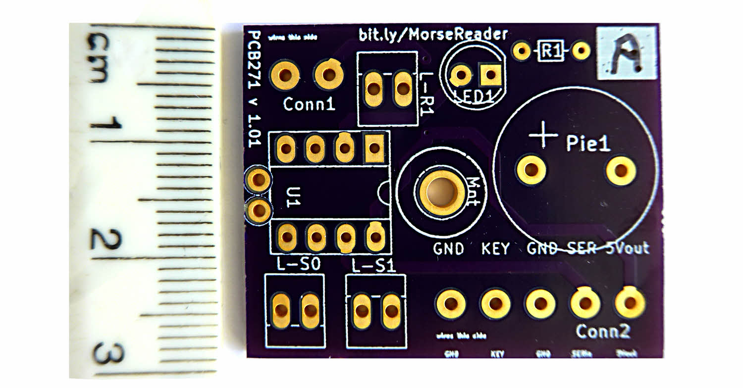
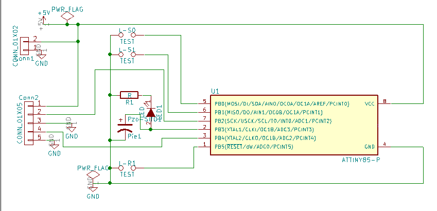
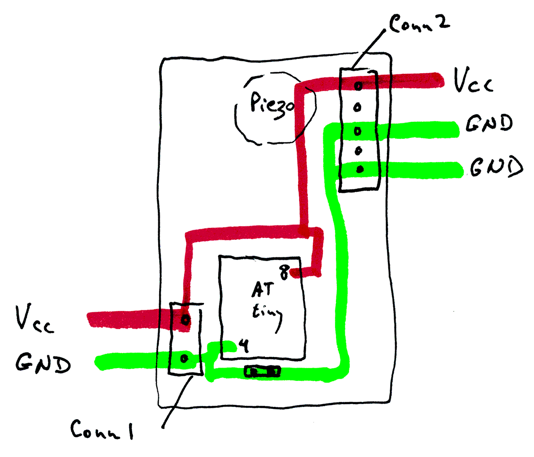
There are two pads intended for a 0.15" pitch screw terminal connector, "Conn1". (You can, of course, just solder wires directly to the pads. This connector is for the Vcc and ground connections.)
Those pads connect to pins 8 and 4 of the ATtiny. In future, I will indicate the pin associations thus: ((8)) and ((4)). (They also connect to three pads on Conn2, lower right. More on this later.)
GPIO lines PB0 and PB1, ((5)) and ((6)) are brought to two pairs of pads 0.1" apart, the other pad in each pair connecting to ground. These are easily supplied with pins and linking "jumper hats", if you want to use PB0 and PB1 for feature-selecting in your application. Or the pads can be used for connecting wires to off-board devices.
PB5, which is also the Reset input ("Not-Reset", strictly speaking, of course!)- ((1)) is brought to another pair of pads 0.1" apart, the second pad again connecting to ground.
The board can carry a resistor, an LED, and a self-oscillating piezo buzzer. (You could leave either or both out.) If you choose to incorporate them (or something similar, of course), they would be driven by PB3 ((2)). From vers 1.02 of the board, there is also a pad you can solder a wire to. The pad connects directly to PB3.
The other two GPIO pins, PB2 and PB4 ((7)), ((3)), occupy two positions in a row of five pads 0.15" apart, intended for a 5 way screw terminal. (Conn2, lower right.) Two of the other positions connect to the circuit's ground, and the remaining position carried Vcc from the board.
A picture is, of course, worth a thousand words, so here's 2,000 worth. If they are unclear in your browser, right-click on them, use "Save image as...", and view them with a simple image viewer, e.g. the excellent free one from IrfanView.com.
A first batch of PCBs has been received and passed testing as a board to carry Edgar Bonet's Morse Code Reader. At time of writing, one was "spare", if you want it. A second batch (minor tidies) should be with me by the end of April.
Edgar Bonet's Morse Code Reader: You tap Morse on a Morse key (or microswitch, if no key to hand!), and the ATtiny decodes it, sends a stream of serial data to something that can display it. An Arduino development system works fine, if you have a "smart cable", i.e. one of the ones with a USB to serial converter in it.) OR you can display what the data says on a stand-alone, serially driven LCD... about $25. See Arduino Morse Code Reading Challenge.
It you are interested in obtaining one, with the tiresome components, if you wish, please get in touch. Board? About $3. Parts? At my cost. I can't send one "instantly", but the level of interest will determine the level of energy I put into the next phase. Sound like vaporware? No, not really. A close cousin, perhaps... but I am not a commercial operation. Just a hobbyist with a "day job", etc. (Contact details below.) At the time of writing, I have one board and 9 programmed ATtinys in stock. More boards have been ordered, and should be with me before the end of April. (If interested in board plus parts, please let me know asap, no obligation... so I can order in the parts.)
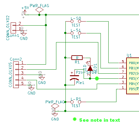
... and, again, with the main elements blown up for easier viewing...
_ _ _ _ _ _ _ _ _ _ _ _ _ _ _ _ _ _ _ _ _ _ _ _ _ _ _
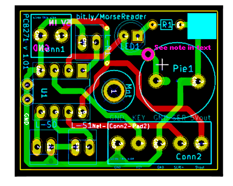
The illustrations above were prepared from the project when it was at version 1.01. From vers 1.02, there was an extra pad, to make connecting to pin 2 of the ATtiny simple, if not elegant. (Previously, it was dedicated solely to driving the LED and piezo buzzer on PCB271 (if present).) That extra pad, present from vers 1.02, has been added "by hand" to the lower two illustrations- in lime green on the schematic, and magenta on the PCB.
There are two sets of pads on the board, Conn1 (2 pads) and Conn2 (5 pads). Generally speaking, I would recommend fitting them with screw terminals, but of course that is not essential.
You may or may not use all of the connections provided for, depending on what external circuits you connect to the breakout board.
This section of this page is to stress something about what I was thinking when I designed the board.
The board must be connected to Vcc and GND from a source of power.
As in all "ordinary" electronics, all parts of the broader circuit, i.e PCB271 and the things connected to it, must have their grounds interconnected. All of the three points marked "GND" in PCB271's various diagrams are interconnected. If you want to connect something's ground, you can connect it to the PCB at any of the three easily available places. (Or, if you are "getting fancy", a number of other places, as well, of course.)
The board also has two places marked Vcc. NOTA BENE: You should NOT connect two SOURCES of Vcc to the board. You must connect one source. You can connect it to either of the places marked Vcc. You won't always need the other one. But the only thing you should use it for, if you use it at all, is for passing the source of power on to some other part of the broader circuit. You can use the second Vcc place as a way to "pass on" the voltage from whatever's connected to the first Vcc place.
If you want a copy of the board, go to the page about getting parts for PCB271-Morse Decoder, and ignore most of what you see there... just use the bits about ordering the PCB.
I would welcome news of any use you put the PCB to... especially if it comes with a photo, and permission to mention here. By all means give me with that any website, blog, etc, you want publicity for.
If you found this of interest, please mention in forums, give it a Facebook "like", Google "Plus", or whatever. I've almost given up writing these pages, because it seems they are seldom read, and of course not every reader will use them... so... is there any point? If you want more of this stuff, help!?
In addition to the tutorials for which this page serves as Table of Contents, I have other sites with material you might find useful.....
Sequenced set of tutorials on Arduino programming and electronics interfacing.
Tutorials about the free database supplied with Open Office version 2.
(If you experienced Adabas with Star Office, ooBase is nothing like it!)
Some pages for programmers.
Using the parallel port of a Windows computer.
If you visit 1&1's site from here, it helps me. They host my website, and I wouldn't put this link up for them if I wasn't happy with their service.
Click here to visit editor's Sheepdog Software (tm) freeware, shareware pages.
Click here to visit the homepage of my biggest site.
Click here to visit the homepage of Sheepdogsoftware.co.uk. Apologies if the "?frmAtTinyPCB271" I added to that link causes your browser problems. Please let me know, if so?
![]() Page tested for compliance with INDUSTRY (not MS-only) standards, using the free, publicly accessible validator at validator.w3.org
Page tested for compliance with INDUSTRY (not MS-only) standards, using the free, publicly accessible validator at validator.w3.org
....... P a g e . . . E n d s .....