I like DIGITAL things... they are "on" or "off". Right or wrong. No messy "gray areas".
Sadly, even in the cozy world of Arduino, not all is digital.
The device needs power.
This essay will help you with getting the powering of your Arduino project right, so that things work.
To make something electronic work, you hook up a voltage. As a result, current flows. How much current depends on the resistance the voltage and the current encounter. (And, to be complete, how much impedance. Close cousin of "resistance".)
What I just says pretty well covers "everything" electrical or electronic. And you may think you "know all about" voltage, current, and resistance. (And you could be one of the many who thought that, and then discovered that while they could pass tests, they still didn't understand those concepts enough, or mis-understood bits.
Just saying.
Power is a derived concept. One that I don't understand very well, to be honest. But I understand it well enough to make things.
Power is "a combination" of voltage and current. You still have a lot of "power" if you have either...
- a lot of voltage (but not much current), or
- a lot of current (but not much voltage).
(You also have a lot of power... a LOT of power... if you have a lot of both.)
Voltage comes from cells, batteries and power supplies.
"They" assume that you "just know" that a given source of voltage can only supply that voltage if you doing connect it with something that has so little resistance that the current which should flow would be too big for the voltage source in question.
If you do make such a connection, you will have exceeded the power rating of the voltage source, and all bets are off. At best, it won't give you the voltage it should. At not-so-good, you may wreck it. It may not work again. At worst, you can cause a fire.
Most power supplies are marked with the voltage they are supposed to produce, and a current, which will be measured in amps or milliamps. A simple charger for a cell phone might be marked "5v, 500 mA". That does not mean that if you hook it up to something a current of 500 mA will flow. It means that if your circuit has so little resistance that a voltage of 5v would cause a current in excess of 500 mA, then this power supply is not suitable for your circuit.
Right... Arduinos...
Arduinos cannot be used to "run", to "power" big, strong, "powerful" (in the narrow electronics sense, as well as the general usage of the term) devices directly.
This essay will help you some with how to power them in-directly, and a lot (I hope) with how much, where, is "too much".
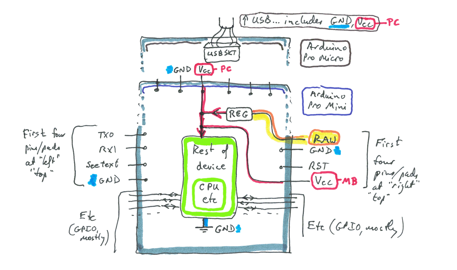
The information here, by the way, is written up with specific reference to the Arduino Pro Mini and the Arduino Pro Micro. The material you need to master will vary somewhat in the case of other forms of Arduino, but what you read here should give you a sound footing for seeking answers in your environment.
Voltage isn't the who story of power... but it is part of it.
Arduinos run, usually, on 5v or 3v3. Whatever voltage your Arduino is using, anything with that voltage present is marked "Vcc" in the following diagrams, and Vcc refers to such parts in the text here.
It may appear that there's a lot to understand in that. Don't worry... none of it is "hard". I'll take you through it.
One simple matter, to kick things off... "GND" appears in many places on both of my diagrams. They are all connected to one another. Not a big deal, but be aware of that.
As I mentioned earlier, in this I am taking the Arduino Pro Mini and Arduino Pro Micro as my examples. They are "the same" for our purposes apart from a few details.
One minor detail: The third pin "down", on the "left" edge of the board, as I am showing the board, is connected to...
- RST if you are using a mini,
- GND if you are using a micro
(RST... more properly /RST, of course, is unrelated to the "power" issues I am discussing here... but I mention it in passing. The left hand /RST pad/ pin of the mini connects to the right hand pad of that Arduino.)
The "top" edge of a mini is populated with a 6-way connector typically taken to an FTDI breakout USB/ serial cable. You have to choose the cable carefully, sending 5v or 3v3 to the Arduino, as appropriate for it's Vcc to the third pin across the top, from the left. The second pin across the top is the one for GND.
The "top" edge of a micro is populated with a socket for a very small USB plug. And here my essay-writing hits a nasty bump in the road. Sigh. The USB cable that you plug into the Arduino's socket will be carrying 5 volts. So if your Arduino's Vcc is 3v3, there will be some level shifting somewhere on the Arduino. This matter will require elucidation... I'm sorry. But much of what follows is still useful! (Noticed this problem late in the drafting process. I will try to come back to it. Remind me of the problem, if it remains, November 2018, please?)
So.. the top edge of the mini and the micro are different. That's why there are two "tops" to the diagram above.
If you ignore the "top top", the one that shows how things are for a Arduino Pro Micro, then ALL of the rest of this essay, and the diagrams, are 100% okay (as far as I know!). How/ where the 5v from the USB cable, when present, feeding a 3v3 Micro becomes 3v3, I'm not yet sure. Allow for that.
If you have nothing connected to the top edge of the Arduino... Mini or Micro, then you need to supply it with Vcc some other way.
If you have a regulated 3v3 or 5v, depending on what you Arduino needs, you can "plug it in" via the 4th pad from the top, right hand side. The pad marked Vcc. ("Regulated": It doesn't vary much, regardless of changes to the resistance in the circuit it is connected to.)
If you don't have a regulated Vcc, you can connect a different voltage to the top pad from the top, right hand side, the "RAW" input.
You can see from the diagram how various things are connected together.
You would never use the "RAW" pad for anything other than supplying a voltage to the device. It must be at least a little more than your Vcc. A spec sheet I saw for the Mini said it could be as high as 16 v, but I'd stay well away from that, if I were you. 12v would make me nervous, but I would try it if I "needed" to use 12v. (I'd look out immediately, and subsequently, for things on the Arduino getting hot.)
I would never try to use the RAW pad as a source of voltage. (Although, as we will see later, I can see good reason to connect the RAW pad and other things (external to the Arduino) to a source of voltage.)
I can anticipate no circumstance where I would want to try to treat any of the pins on the top of the board as a source of voltage.
The previous statements may have seemed odd to you. But perhaps the next one will clarify why I made them...
Sometimes I use it as a way to put Vcc INTO an Arduino... and sometimes I use it as a source of a little current, driven at Vcc.
Look at the diagram, and think about that.
If Vcc is being supplied from either the pad at the top of the board, or from the "downstream" side of "REG", the regulator which creates the board's Vcc from RAW (when that is present), then you can connect the Vcc pad to things outside the Arduino that need a source of voltage, can't you?
If you are NOT supplying Vcc either of the ways just mentioned, then you use the 4th pad down supply the Arduino with the Vcc it needs.
A detail: I would try, by the way, to always have only one source of voltage connected to the Arduino. In other words, I'd avoid having a source of voltage connected at the top edge when RAW or the Vcc on the right edge had a voltage connected. I'd avoid having a source of voltage attached to RAW or the Vcc on the right edge.
"In theory", I suppose, if you were using a 5v Arduino, you could have 5v coming in at the top over the cable, AND a source of 5v connected to the Vcc pad on the right edge. But what if one of the sources wasn't supplying exactly 5v? I don't know. So I'll avoid the possibility of creating a problem that way. (Avoiding it isn't hard, thankfully. (I haven't gone through all the combinations that would create two sources of Vcc being fed to the chip. Avoid all of them!)
Right! That's the basics. Now some more detail.
I said that if the voltage for the Arduino is NOT being supplied to it via the 4th pin down on the right side, not being supplied via hat "Vcc" pad, then I would be happy to use that pad as a source of Vcc to drive a few, high resistance, external-to-the-Arduino circuits.
And I am. (Happy to use it thus.)
But be careful, especially if you are using an Arduino Micro, and powering it via the "RAW" pad.
The RAW pad supplies a voltage to the voltage regulator on the Arduino. (Shown as a rectangle marked "REG" in the diagram above.)
That regulator, in an Arduino Pro Mini, is only "rated", i.e. "good for" up to 150 mA. (And it is always a bad idea to use a device near it's rating. The rating is the maximum it should experience. That's not the same thing as a level it is happy operating at. Stress it, and you may shorten its life.)
(The regulator in the Arduino Pro Micro is rated for 500 mA.)
And not all of that current is available to you for the things you want going on outside of the Arduino... the Arduino's needs must be satisfied as well.
Even if you are using a 5v Arduino, and supplying a high- current- capable Vcc via the pad on the top edge... which, as you see in the diagram, connects directly to the Vcc pad on the right side... don't go crazy with the current you draw. There are limits to the current that the tracks on the PCB can handle.
Do not despair!
Arduinos can control circuits that need a lot of current. Just not the way you might have tried to do it, if you hadn't read this essay. (Letting a low resistance external circuit encourage a high current can fry your Arduino, by the way. Though sometimes you'll get lucky and only fry a single GPIO line.)
And at the same time as we "step up" to using high (-ish) currents, we can also cast off the shackles of the Vcc the Arduino is using (3v3 or 5v).
Don't, by the way, take anything I've written on the web as encouragement to use household voltages. I don't know enough to do it myself, so my writings certainly don't tell you enough. I do know that mistakes with household voltages can cause fires. And invalidate insurance policies, if the prospect of a fire or fatality leaves you feeling "I'll give it a try."
But if you want to use 12, or even 24 volts for some reason, that's possible. (Even 3v3, if your power source is up to it, can cause fires... but most low voltage sources are also, happily, only capable of low currents. (Low voltage sources OTHER THAN Lipo cells, that is. THEY can generate very high currents if short circuited. High currents can cause fires.... hence all the concern about Lipo in the mail or in airplanes.) Low currents, low amounts of heat, generally speaking. But Mr. Murphy is very resourceful... Try to THINK. "What could happen here?")
The following addresses several things at once...
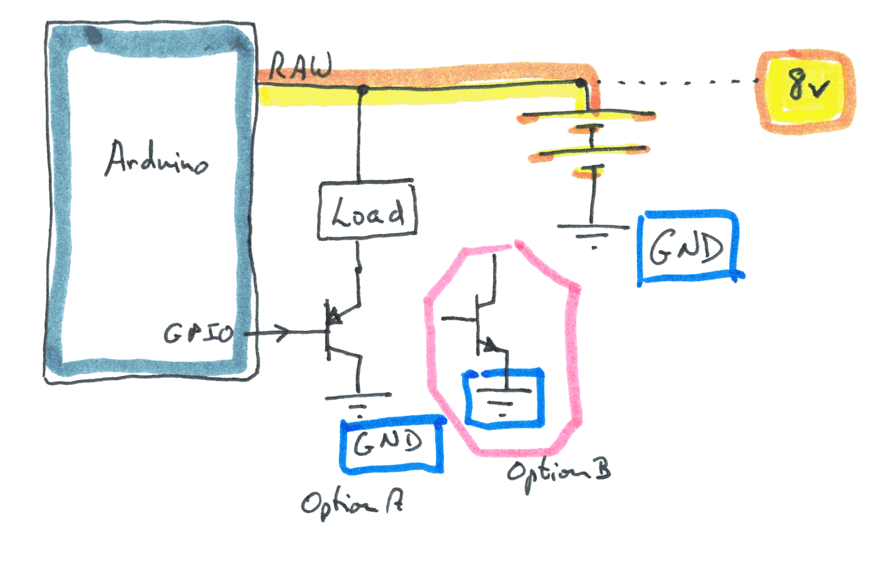
I've shown an Arduino powered via the "RAW" input. I happen, here, to be giving that 8 v. (From the battery... the two long, two short horizontal lines. (I don't think you can MAKE 8 v from a (chemical) battery... the "battery" was just to show "a source of 8 v".)
That 8 v is ALSO going to what I've drawn in as "Load". The "load" can be anything! It is the thing this project "runs", that this project "turns on and off".
Below the load: A transistor.
Now. I'm not very good with transistors. They come in two sorts... NPN and PNP. I've drawn one of each. The "option B", in the box, is there to say, "you may need this sort of transistor" for this job."
Sorry!
And different "load" devices will allow different amounts of current to flow through them. And that current will flow through parts of the transistor. And if the current is high, you'll need a different transistor than you might use if the current were low!
One thing I DO know about transistors: The current in or out of the Arduino, via the GPIO can be very small and still do the job. (You may want a resistor between the Arduino's GPIO and the transistor. Sorry for that additional gray area.)
And this is good! Because, though it isn't at the heart of this essay, it is related. The Arduino itself has power limitations. Something like... look up elsewhere!... no more than 20mA over any GPIO pin, and no more than 200mA as the total flowing in all of the GPIO pins.
If you are NOT powering the Arduino via RAW, you can still connect a circuit like the one in the most recent diagram MINUS the connection to "RAW". In other words, via a transistor, you can use an Arduino to control the operation of a load which is running on, say, 8v.
In spite of my ignorance in transistors, I hope the information was helpful? It is now 10pm, and I want dinner! By all means email me (see below) if you see problems or have questions.
If you visit 1&1's site from here, it helps me. They host my website, and I wouldn't put this link up for them if I wasn't happy with their service.
Click here to visit editor's Sheepdog Software (tm) freeware, shareware pages.. Material on this page © TK Boyd 10/18
Click here to visit the homepage of my biggest site.
Click here to visit the homepage of Sheepdogsoftware.co.uk. Apologies if the "?FrmAht" I added to that link causes your browser problems. Please let me know, if so?
![]() Page WILL BE tested for compliance with INDUSTRY (not MS-only) standards, using the free, publicly accessible validator at validator.w3.org
Page WILL BE tested for compliance with INDUSTRY (not MS-only) standards, using the free, publicly accessible validator at validator.w3.org
....... P a g e . . . E n d s .....