Breadboards are great! They certainly have their place in the electronics hobbyist's life.
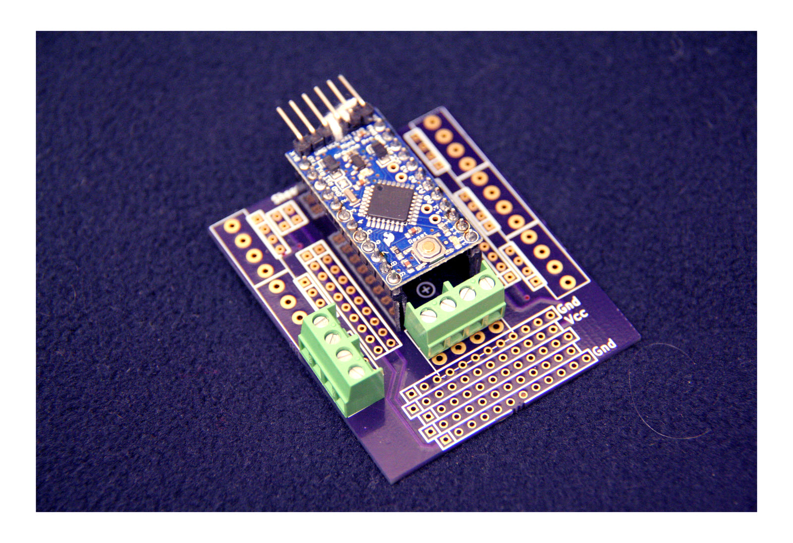
In the meantime, here's a "middle ground"... a simple, inexpensive PCB to bring almost all of the pins of an Arduino Pro Mini out to solder pads. The pads are done so that they can be populated with screw terminals, if you want the extra flexiblilty they offer for the minimal extra expense.
You can buy (about $8 each at 1/20) copies of the board from OSHPark.com. (The link takes you to a "product page". The price there is the current now price for three copies of the board... OSHPark's minimum order. That includes p&p.) (More details at end of page.)
A breadboard is great for development work, maybe even for a project that isn't terribly important. As a long-term solution for making up a circuit, they aren't very robust. Like most short-cuts, they will lead to tears if you use them in inappropriate circumstances.
The board also has significant areas of "breadboard like" pads for your use, and a generous allotment of pads carrying both Vcc and Gnd.
The boards are intended to make it easy for you to "make up" instances of "finished projects" with soldered connections which are immune to the lack of robustness suffered by breadboard based circuits.
You plug an Arduino Pro Mini into the board (it occupies the area shown in green.) Apart from a "few little wrinkles", the boards merely give you two pads for each of the Arduino Pro Mini pins, in the same order. (One pad (columns B and J) for an ordinary wire, the other (columns A and K) for screw terminals).
You are very welcome to use the design. You can order the board, pre-drilled. (Details follow. They cost about $8 each, but the mfg will only accept orders for 3 or more. Price includes p&p (11/15 price).
But! You are responsible for any consequences!
I am not aware of flaws in the board, except as set out below, but it hasn't been around very long. And, more especially, I can't know what connections you are going to make, can I?
Please get in touch if you discover any flaws in the board, or any ways to go wrong. How are using it would also be of interest.
The basic idea of PCB264 is that it gives you a way to connect an Arduino Pro Mini to "other stuff".
The Arduino Pro Mini plugs into a socket on PCB264. (The pads in columns E and G. The Arduino covers the area shown in green.) This, among other things, makes it easy to swap out "the heart" of a project... if you have more than one Arduino Pro Mini!
When you've done that, through PCB264, you have easy access to all of the "lines" of the Arduino Pro Mini, even the four "inside" the two main rows of pins (the pads in column "f"). If you've chosen to add screw terminals to the PCB, you even have them available via screw terminals. (Columns A and K) (Alternatively, or in addition there are solder pads for ordinary wires. (Columns B and J))
A tour of details follows two sections of warnings
I always worry when working with Arduinos (and other things) about accidentally connecting two sources of a voltage.
In the case of vers 1.00 of PCB264, I intended (there are ways to go around that) that the power would arrive for the Arduino Pro Mini via the pins along the narrow edge of it. And that all power for all of the connected electronics would derive from the power supplied thus. (From vers 1.02, I've made it easier for you to make a different... but more risky... choice. Be careful!)
So, when you have a "programming cable" attached, everything has power.
If, for your target use of the system, you don't want to tie up a full blown programming cable, I suggest you make up a cable which takes the 5v and the Gnd from a USB plug and supplies it to a socket on a cable to plug onto the "programming" pins of the Arduino Pro Mini. Like this, it will be easy to switch between "programming" and "using", with minimal danger of accidentally connecting two power sources at the same time.
Beware, as ever, exceeding the power the device is capable of handling.
All that may sound a little scary... but it all "applies" whether you use PCB264 or a breadboard... so learn the things you need to know, and don't let the warnings scare you off PCB264!
A further matter on the subject of "power": With no Arduino Pro Mini plugged in, in verds 1.00 of the board, the "ground rail" of the PCB is TWO ground rails. The design relies on a connection within the Arduino Pro Mini to connect the two otherwise separate ground rails. In vers 1.02 (and higher) the "two" ground rails on the PCB are connected on the PCB, and "throuh" pins 4 and 23.
In version 1.00, I made a little boo-boo.
The two circles with "+" signs in them in the silkscreen, near the center of the board, were meant to be two holes, for mounting the PCB. Get your drill out, and fix, if you want a mounting hole. Not a deal-breaker, I hope? (^_^) (It is only a two sided board... there is nothing "inside" it you might damage.)
In version 1.00 (see silkscreen), I messed up.
See "B" on the illustration. There are two rows of 4 large pads "below" the socket for the Arduino.
That was meant to be one row of large pads (for screw terminals) and one row of small pads for wires.
Each column of two pads connect to each other and nowhere else in vers 1.00 of the board. These pad pairs connecting the four "inside" pads of the Arduino Pro Mini to screw terminals, but you'll need to add wires to the vers 1.00 board to achieve this. A fairly trivial chore. If you don't add those wires, then of course, you can use the four pairs of connected pads for whatever want you wish to assuage. Connect something from the outside world to the board, but not directly to a pin of the Arduino Pro Mini on arrival, for instance?
I should mention that there are minor differences between vers 1.00 and what is on the drawing board for the next version, probably 1.02, if it gets out the door. Vers 1.00 doesn't offer the "disconnects" for Vcc and Vraw. AND it has some wrong **labels** on the back side. Just scrape off the "Vcc" and two instances of "Gnd" to prevent confusion. The circuits are fine, it is only the labels, and only those on the back, that are in error.
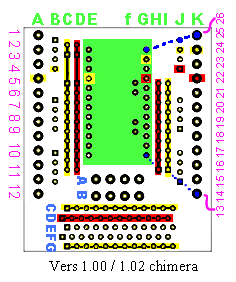
The illustration at 11/15 does not EXACTLY match vers 1.00 of the board, of which 3 copies had at that point been produced, nor vers 1.02, which only existed on my hard disk... hence the label on it "Vers 1.00 / 1.02 chimera". (If that's missing from the illustration, please contact me and tell me to revise this text!)
The differences were, I hope trivial... a few pads moved, a few introduced. But a big re-check should be done in due course, I suppose. I did a big check with a vers 1.00 board.
Turn the board as it appears in the illustration. You may want to open a copy of this page in a separate window (right click on the link for an easy way to do that, in Windows/ Firefox anyway), scroll down to the illustration, and arrange your screen so that you can see both at once, scroll one, leave the other showing the illustration.
In column A on the left edge: 12 large pads. These all connect to pins of the Arduino, "copying" the left edge of the Arduino.
They are large, in case you want to populate the pads with screw terminals. There is nothing significant in the fact that the twelve pads are in 3 groups of 4.
Just inside column A, we have column B, another set of twelve pads, each attached to the corresponding pad in column A, and pin in column E.
Note the two columns of magenta numbers... 1 down to 12 on the left, 26 down to 13 on the right. These are to number the "rows"... but the "rows" are not horizontal, because of the different spacing of the pads in the different columns. The pads in the four columns shown with yellow or red highlights, columns C, D, H and I (which we WILL come to!) are not included in this numbering.
Turning for a moment to the right hand edge of the board, columns K, J and G correspond to their mirror images on the left hand edge. The diagonal dotted blue lines try to re-cap this idea of the connections. Using the magenta "row" numbers just mentioned, I can "point" to where I've done the blue lines: They show the connections in rows 26 (top right) and 13 (lower right). N.B.: The pins in row 13 do NOT connect to either the red or the yellow column pads.
The red and yellow marked pads: There are a lot of pads on the illustration marked red or yellow.
All of the pads marked red are connected to the Vcc that is present in the circuit.
All of the pads marked yellow are connected to the circuit's Gnd... IF an Arduino Pro Mini is plugged into the PCB. (The design relies on a connection inside the Arduino Pro Mini between its pins 4 and 23 to connect the "two" Gnd rails of the PCB.)
This "all of the pads marked..." includes the two three colored rows of pads in the "general breadboard" space at the bottom of the board, and a few of the pins in columns A, B, E, G J and K.
That covers pretty well all of the pads... except the two rows marked A and B, which we discussed elsewhere. (The two pads in each column connect to each other, and it is intended, eventually, to connect each column to one of the "inside" pads of the Arduino Pro Mini... but you may want to cut that trace, if present, if you are not using the inside pads, and want the 8 in rows A and B for general purpose use. I can think if no reason NOT to go this route.
I had my PCB made for me, from my own KiCad-generated files, by OSH Park, of the USA. I've used them before, am happy with their service. The following link will take you to PCB264's vers 1.00's page at OSHPark.com.
You can order my board direct from them. At the moment, I fear you can only order version 1.00 of the board, but, apart from a few lacks (see below), and bad labels on the back side, it is fine. (Just scrape the labels off. The circuits are fine.) Note: Minimuim order: 3 boards, @ about $8 each, incl p&p to anywhere. Reasonable speed, to the UK, anyway. (Very good inside USA, where boards are made.)
Lacks: The traces between the "inside" pads of the Arduino Pro Mini, which you may not even want, are lacking. You can use wires. A way to disconnect Vcc and Vraw is lacking. They might only lead you to unwise configurations anyway. Other than that, vers 1.00 is fine.
So... to order the board... (If you find that has changed, as it will if I eventually go the trouble of pushing out vers 1.02, and this text isn't changed, please get in touch?)
The following link will take you to PCB264's vers 1.00's page at OSHPark.com. It might pay you to do a search of the shared projects on "PCB264", in case I've released a later version, and failed to update this... in which case, please let me know?
(You might also find PCB265- a little board I did for connecting wires to the end of a bit of Cat5 cable. Page planed for that in due course... this mostly to help me remember the link, to be honest!)
If you like what you see there, you can go ahead and order THREE copies of the board, post "free" to anywhere in the world. You would be dealing with OSHPark alone... I wouldn't be involved.
Other than the PCB, you only need "a socket" to plug the Arduino Pro Mini into, and, maybe (if you want them) the screw terminals.
For the Arduino Pro Mini, I just use two 12 socket "bits" of some 0.1" (aka 2.54 mm) single row female header strips. Easily available, usually in 40 socket strips, via the usual channels. Beware the "low profile" type. Other than that, hard to go wrong. I've never met a strip which could not be cut down. You lose one socket in the process, and it is worth carefully trimming the cut end.
The screw terminals blocks are (almost) equally unremarkable. Be sure to buy ones with 0.15" between the pins (3.81 mm)), though, and be sure their design allows "stacking" multiple blocks, end to end. I happened to be buying in the UK, used http://www.rapidonline.com/, their part number 21-4486
I would welcome news of any use you put the PCB to... especially if it comes with a photo, and permission to mention here. By all means give me with that any website, blog, etc, you want publicity for.
If you found this of interest, please mention in fora, give it a Facebook "like", Google "Plus", or whatever. I've almost given up writing these pages, because it seems they are seldom read, and of course not every reader will use them... so... is there any point? If you want more of this stuff, help!?
Click here to visit my main homepage where you
can explore other areas, such as education, programming, investing.
How to email or write this page's editor, Tom Boyd. Please cite "pcb264-arduino-pro-mini-to-screw-term.htm".
![]() Page has been tested for compliance with INDUSTRY (not MS-only) standards, using the free, publicly accessible validator at validator.w3.org. Mostly passes.
Page has been tested for compliance with INDUSTRY (not MS-only) standards, using the free, publicly accessible validator at validator.w3.org. Mostly passes.
AND passes...
