This page created in January 2017. The Sparkfun ESP8266 "Thing" (link to Sparkfun's product page) has been around for a while at that time. It is just one of many ways to enjoy the ESP8266 chip.
If you just want the source code then the ALMOSTlatest and greatest version (Mk3) is available as a .zip file with the various "bits" of the Arduino code needed to compile an Arduserver to run in a Sparkfun ESP8266 "Thing". An even better version became available 24 Mar 19... see notes at "bottom" of page (above big circuit diagram) regarding "ar794". But you really ought at least to skim this page. I know, "real engineers" don't RTFM... but, just once, do it the easy way?
I've prepared a more general introduction to the ESP 8266 Thing for you, if that's what you want. This page talks about an implementation of my Arduserver idea on a "Thing".
2/19, I released a "Far Watch Watcher" ("FWW")for the Arduserver described in this article. (Or indeed, any webserver returning a line somewhere with data from sensors, in the right format! (Format explained in Watcher's page.) It is free Windows software, to run on any computer that can connect to a suitable server (such as some of the Arduservers described here), and plot graphs of the data being returned by the server.
As long as the server presents data in "hhhhsttthhhhstttb" format, the FarWatchWatcher will be suitable.
The more robust, more user friendly early version of the FWW software only plots the two sddd values, and it assumes they report a temperature, in DECI-degrees Celsius. (If the application gets 184 from the Arduserver, it will plot it as 18.4 degrees Celsius.) A more advanced version. More advanced also means more hassle to set up.. not a LOT of hassle, but some.
The applications are "configured" via ini files.
Obviously, you have to tell it where to find the Arduserver on the LAN or WAN. This is done with the [MainElements]/ IPAdd and Page entries. In addition, one small tweak may be necessary. If the source of the page returned by the Arduserver gives you the data on its line 5 (counting the first line as "1"), then in the ini file, set [MainElements]/ WhereFmtCodeLineIs to 4. (or is it 3? or 5?.. sorry! At least the application gives you lots of information about what is being seen, etc.)
The Arduserver presented here is capable of MUCH more than "just" reading two temperature sensors and a digital input... but that's all the simple FarWatchWatcher can access for the moment. (The state of a digital input to the Arduserver, and the values in the Arduserver's two counters of external pulses are also available in machine-friendly form from the Arduserver.)
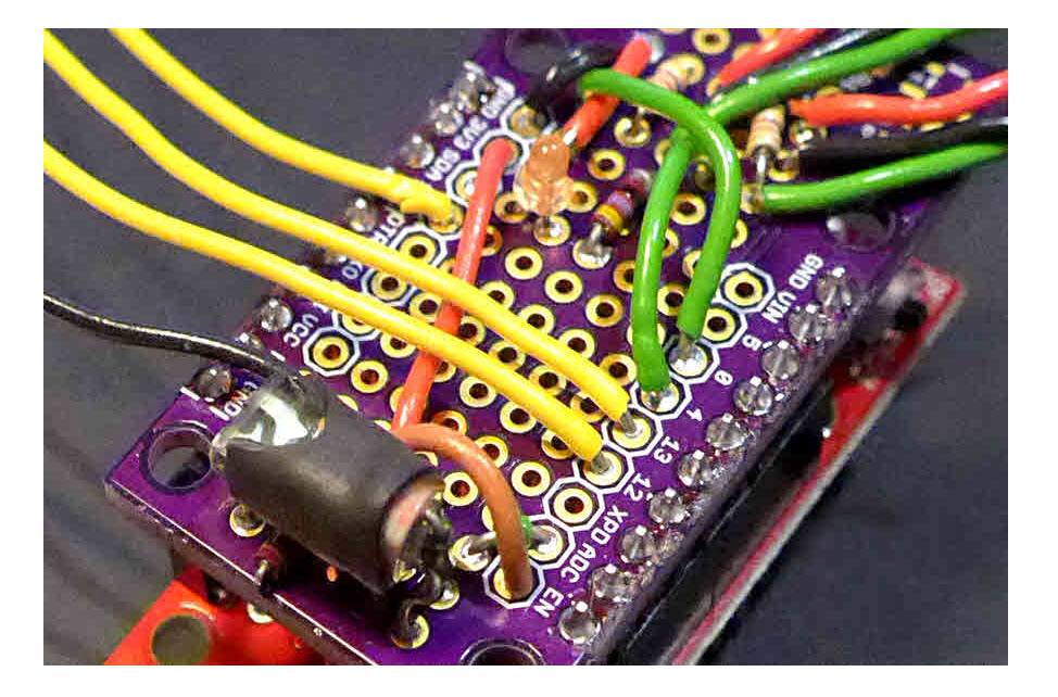
With the code you can download (see below), a Sparkfun ESP8266, a few sensors, notably a DS18B20, you can set up a web-server with inputs and outputs which you can read or set/clear from across the web!
Setting up the ESP8266 to respond to enquiries from browsers is not, in itself terribly complicated. Nor, because of the ESP8266, not an expensive exercise. $16 for the ESP8266, and not as much again for the sensors, etc, you will connect to it... most of that will be for the temperature sensors. Get just one, if you don't feel the need of two.
A lot of the explanation is in comments in the sourcecode.
However... in order to get one "visible" outside of your own LAN, you will have to master all of the basic elements of putting anything on the internet. (The same series of pages also addresses the less complicated issues of getting a server visible inside your LAN.)
If you haven't worked much with IP addresses, DDNS, ports, servers: Scan what is below, and say to yourself "That sounds fun"... and then go off to the pages about putting things on the internet. You will thank me, in the long run! Or waste a lot of time learning the ropes the hard way, as I did... gathering "scraps" of knowledge in the wrong order!
As with any Arduserver, there is an LED you can turn on and off. (The commands are /led/1 and /led/0) And it shines on a light sensor, and you can "see" what the sensor reading with the /read command. So... watch the value reported by read change after you have changed the state of the LED. (Yes, it is basically a "home made optocoupler").
In addition, this Arduserver has two temperature sensors, and two "counters".
The counters can be used for things like windspeed sensors. Anything that switches a switch on/ off/ on/ off/....
The "counter" will tell you how many times the state of its input has changed. If the many uses don't occur to you, trust me: There are LOTS of uses! There are LEDs on the system that tell you, if you are in the place the Arduserver is, what the state on the inputs to the counters are. These are separate, electronically, from the inputs themselves.
There's also a digital input to the ESP8266 which has been provided for in the software. You can see the state of that input across the internet.
Yes! I have several you might find working on any given day. If when you click on the links below, you get sensible "stuff", instead of "page not found", or "can't connect", the "stuff" has come from an ESP8266 running my Arduserver code. Don't be fooled into thinking that you've "only" accessed an "ordinary" web page!
If it is still up... it comes and goes, of course, as any hobbyist device does... you can access my first ESP8266 Arduserver.
And there are two more: my second "Thing" Arduserver, and, on the same LAN, my third instance of this design.
If none of them are working just now(!), here's a bit of what you would see. the following. The link in the second paragraph (disabled here) would take you to this page, if you were looking at the page by going to the Arduserver for it.
Created early Jan 2017, using the wonderful ESP8266 Thing from Sparkfun, and the software provided by them and by others. (See code)
The hardware that is serving this page cost $16. For details, see my page with the details, including the sourcecode, for the server this comes from.
An Arduserver is a little demo of how you can set up a small web-server which will allow someone with a browser to control outputs and read inputs remotely, across the internet with nothing more than a browser.
Furthermore, due to the following two odd lines, the Arduserver is machine friendly, and data can be read from the Arduserver by programs running in computers elsewhere. So, for instance, if you wanted an alarm to ring at location A when the temperature at location B dropped below say, 40 degrees Fahrenheit, that could be arranged if you had an Arduserver at B, and an automatic Watch the Arduserver program running at A.
hhhhsttthhhhstttb
0041+2210287+2421
Analog Pin = 750
Digital Pin 12 = 1
1-123456789012345678901234567890
2-123456789012345678901234567890
3-123456789012345678901234567890
4-123456789012345678901234567890....
Note particularly in the text above, the line after the "hhhhsttthhhhstttb".
The characters of that are dynamic. In the instance above, the 0041 says that the anemometer on my roof had transmitted 41 pulses to the Arduserver before I accessed it. And the +221 says that the temperature in the room where the Arduserver's room was 22.1 degrees Celsius. The next four ("0287") report the count from the second pulse counter. Then comes "+242"... temperature other sensor sees is +24.2 Celsius. And finally "1": the state of the digital input to the device the software is running on is "high". (That paragraph was written in respect of the first ESP8266 Arduserver. The others have all of the same inputs, but I haven't hooked things up to the counters yet. The second Arduserver's second temperature sensor isn't connected. And none of the temperature sensors on the second and third Arduserver are (yet) someplace interesting! Sorry!)
Why present the numbers in such an arcane format? Because the format is machine friendly. Once the Arduserver is running at location "A", I can have another computer running at location "B" periodically, without any effort on my part, interrogating the Arduserver. It can draw a graph of the windspeed data, and the temperature. And more importantly it can ring an alarm bell if the temperature falls lower than it should, so I can send someone 'round if the heating fails and I am headed towards frozen pipes.
There is more on this concept of a program to watch what the Arduserver is reporting on the page I wrote about that. At 10 Jan 17, the page is dated, but if what you see there is interesting to you, please get in touch?
It seemed like a lot of work to produce this web page, let alone the software you can download from it.
However, credit where due: I only ran the last half mile of the marathon. The software here is an amalgam of the webserver demo from Sparkfun for their ESP8266 Thing ("Dev Board" version... $16), and of some Dallas 1-Wire temperature sensing code for Arduinos. Full credits, webpage references, in the sourcecode.
And those wouldn't have been possible without the prior great work of the ESP8266 community and the Arduino community. And before them, the good people at Dallas Semiconductor, who brought us the excellent 1-Wire.
I won't start on those deserving of credit for WiFi and the internet, which are also used in this, of course.
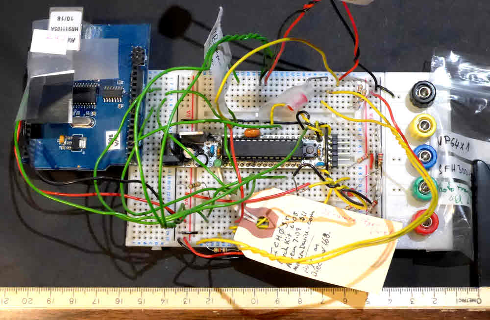
We live in a remarkable age. We've come a long way. My first Arduserver cost about $70, and had to be connected to the LAN with a cable. (The ESP8266 connects to the LAN via WiFi.)
My first Arduserver allowed only a very small web-page to be served... and was a pig to program, because if the web-page got too large, the "fail" wasn't "pretty". Things Just Went Weird.
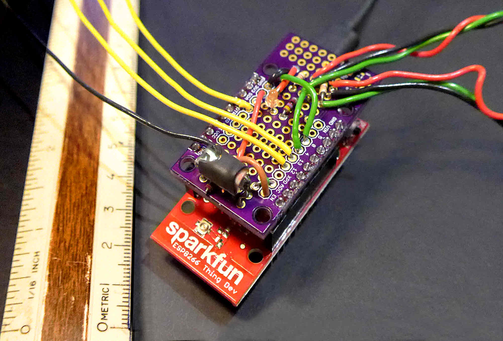
But all that's behind us now! Below you can see "old" and "new", at roughly the same scale...
The fact that you are reading this suggests you probably have what you need, if are reading it at home. In a school, there may be "issues" about connecting things to the network. Talk to your tech people.
And you need an ESP8266. $16. Big deal. Or an Arduino with an interface to your LAN. You'll have to tweak the code, to work with the alternative hardware.
The Arduserver is best installed first as something you access from a PC on the same LAN that the Arduserver is on. Using a numeric, local, IP address... something like "192.168.0.23". There's nothing "special" about any of this. Anything you might attach to the LAN would entail similar issues. An IP-cam(era), for instance.
Once you have it working thus, if you want people to be able to interact with your ESP8266 Arduserver from anywhere on the internet, with any web browser they like (e.g. Firefox), you need a few extra "bits"... but again, like the IP-cam install, there's nothing "special" about installing the Arduserver for such use. You need to put an entry in your router's NAT table, and you need a "dynamic DNS". Explained elsewhere... my pages and other people's. Mine are a bit chaotic... I will try to "organize" them. You could start at my Overview of Using and Creating Servers.... but don't let all THAT put you off! Get the Arduserver working on your LAN.. not especially hard... and the rest, if tedious, is not impossible. (Or expensive!)
You need an ESP8266 connected to a LAN... for "the simple life". The connection is via WiFi.
If you had JUST that, the Arduserver would work! If you connected a wire from the pin marked "12" on the Arduserver to ground, the report in the served page about "Digital Pin 12" would change. (It equals 0 when nothing's connected to pin 12, and 1 when pin 12 is connected to Ground.)
Arduserver will "work" with none, all, or any combination of the following external "bits".
I have indicated the connection to the ESP8266 the software is set up for, but you can change things, up to a point.... and in every case, changing them is merely a matter of changing ONE LINE, e.g.... to make the pin that is monitored as "Digital Pin", you change the following line...
const int DIGITAL_PIN=12; // Digital pin to be read.
Of course, you have to be careful that you don't reassign it to a pin that is already in use for something else!
It probably makes sense to use the ESP8266's pin number 5 to output information to someone looking at the ESP8266, because the ESP8266 has an LED (and resistor) on that line. In the code as presented, I have...
const byte Pin_ShowAnemomInputStatus=5;
(That's badly named... the "Anemom(eter)" input, for which an LED on Pin_ShowAnemomInputStatus shows the state, can be driven by ANYTHING that is essentially a switch, and you want to know how often it opens/closes)
As I was saying... in the code I have...
const byte Pin_ShowAnemomInputStatus=5;
You can put that output elsewhere if you wish to...but you might as well use pin 5 for SOMETHING that an LED can tell you about.
Then there's...
const int ANALOG_PIN=A0;
On the ESP8266, only pin A0 is capable of doing analog to digital conversion. (And it should not be subjected to more than 1.0v.) So you are A Bit Stuck if you would like to move the monitored analog signal elsewhere. You can't.
But there is room for LOTS of flexibility... and remember... you don't have to use all of the inputs and outputs that the software is willing to "drive".
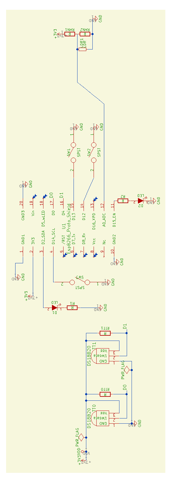
RIGHT CLICK- select "Open in new Window" for a re-sizable, separate copy of the wiring information. Of course, your browser must not be filling your whole screen, if you want to use this aid.
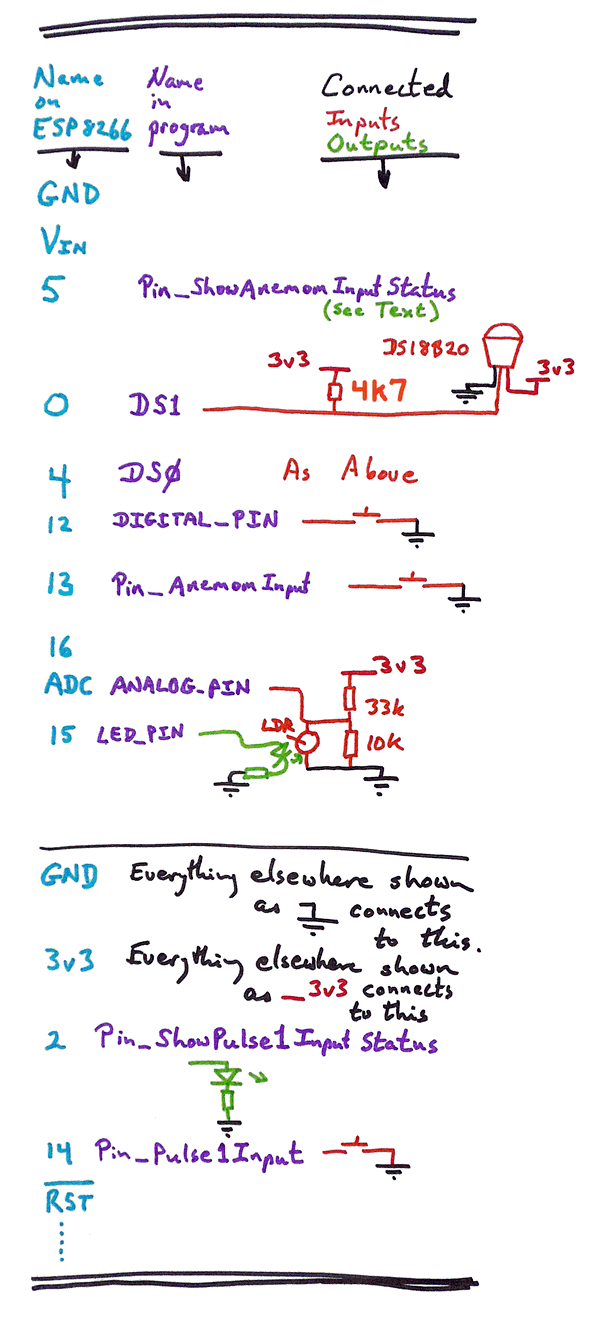
The diagram on the left shows you the things to connect.
On the webpage produced by the software, most of the things you see are reported explicitly, in text.
Although the diagram doesn't SHOW anything "connected" to pin 5, remember that there is an LED (and resistor) ALREADY CONNECTED to that pin, on the ESP8266 board. (It is like the LED on pin 13 of "standard" Arduinos.)
If you use the "/led/1" command, you will turn the LED on "LED_PIN" on. ("led/0" turns it off.)
On my Arduservers, I "stick" the LED on "LED_PIN" up against the LDR ("light dependant resistor"... a crude light sensor) on "ANALOG_PIN". When you use the "/read" command, you are told what the LDR is "seeing", so you can "see" whether you turned the LED on or not, even when you are 5,000 miles from the Arduserver! (It helps to wrap the LED and LDR in some tin foil and tape, to exclude other light.)
(I offer the schematic in another form further down the page.)
In the case of the pin sharing a line with the on-board LED, I wouldn't go over 10mA, if I had an external LED on the pin too.
Whether you connect the resistor to the 3v3 or GND won't make a lot of difference... but if you do, their behavior will be as follows: When the output LOW, the LED will be ON. This will be consistent with the on-board LED. The messages in some older versions of this Arduserver (those before 23 Mar 19) may be 180 degrees out of phase with the LED states. Note that when set up like this, that while the command "led/1" does turn the LED on, it is potentially confusing, because user might think that "led/1" is saying "make the state of the pin controlling the LED "1", i.e. high." But risking that is worth it- to have your external LEDs behave as the on-board LED (on pin 5) behaves.
Signals are sent to the pin defined on the diagram as "LED_PIN" BOTH from the code in the "FromSparkfun" tab of code, and from the Arduserver software.
The "FromSparkfun" code uses the pin as follows:
Typically, you would have an LED on the line. The code switches the line high and low (about 0.1 sedcond each) whyile trying to establish the device on the WiFi network, or while trying to re-establish it.
The "Arduserver" software ALSO uses this output to drive an LED (or other), as directed by /led/0 and /led/1 commands.
Whatever purpose you have in mind for the result of the /led/0 and led/1 commands, it MUST BE TOLERANT of this other operation of the output, unless you take that out of the FromSparkfun code.
The machine friendly line in the page created by the web-server, the one just below "hhhhsttthhhhstttb" reports the following...
First 4 digits: The count of pulses input via Pin_AnemomInput. (Which, as I said, doesn't have to be an anemometer. Bad name.)
First "sttt", e.g. +234 is temperature sensed by Dallas temperature sensing chip (it can be a DS18B20, DS18S20, or DS1822), interpreted thus: +234 indicates + 23.4 degrees Celsius. Sensed by the chip on "ds0".
Second hhhh: The count of pulses input via Pin_Pulse1Input. Note two things: That's "PulseONE", not PulseELL (Anemom was "Pulse0"). And using pins 2 and 14 is okay... as long as you don't ALSO (at the same time) want to use an I2C peripheral.
Then there's the second sttt... another temperature. The one on ds1. (For the two temperature sensing chips, you can also put them on different lines. Change the following to "move" the connection...
OneWire  ds0(4);  // on pin 4 (a 4.7K resistor pull up to the system's 3v3 is necessary, too)
OneWire  ds1(0);  // on pin 0 (a 4.7K resistor pull up to the system's 3v3 is necessary, too)
("ds0(4)" means that for temperature channel "0", the sensor is on pin 4 of the ESP8266.)
And finally... the last character of the string will be a 0 or 1, depending on whether the input to DIGITAL_PIN was low or high, respectively. (If DIGITAL_PIN is connected to nothing, it will be seen as high.)
This essay originally written alongside the building of my first Sparkfun ESP8266 "Thing" Arduserver, January 17.
In February, I started to do more work, with a clone, "the NC ESP Arduserver". In this section I offer some notes on that, and on things I probably should "tidy" here, in the sourcecode, etc...
Trivial: The LED and resistor on pin 15 are the "other way around" on my third Arduserver. (Other way around for what was in diagram here at 06 Feb 17. Pin 15 (assigned to "LED_PIN"), then resistor, then LED. Other side of LED to ground. Search on "digitalWrite(LED_PIN" for the relevant line. (Not line predicated upon "if (val>-OR-EQUAL-TO). The contents of val can be less than zero. It is merely a code for the command issued by the person accessing he Arduserver. See full program listing for details.)
Minor annoyance: At 06 Feb 17, if you give my first or second ESP8266 Arduserver the command ">IP Address</led/0", it turns the LED on, not off. (And led/1 turns it off, not on.) (That was fixed when the third Arduserver was built.)
---
Oh. And the commands are case sensitive. The Arduserver will reject LED/0 or Led/0 as invalid commands.)
Trivial: There are two temperature sensors on the Arduserver. Originally, the one for which all associated entities are identified by "0" at the right hand end of the name were on D4, and all associated with "0" were on D0. E.g. the lines...
ds0(4);
ds1(0);
They (the two lines above) need to be, are in the course of, being changed to ....
ds0(0);
ds1(4);
... so that all of the things NAMED "0" are associated with D0. (It isn't possible or necessary for the "1" items to be associated with D1... but because we ARE using D0 for ONE OF the temperature sensors, it is only sensible to put temperature sensor "0" on that line.)
At 12 Jan 2017, the latest and greatest version (Mk3) is available as a .zip file with the various "bits" of the Arduino code needed to for compile this Arduserver. Be sure to see the note below in "Details, details" about turning the LED on and off.
There are multiple .ino files because I used tabs to make working on the code easier. Just unzip the .zip. It will create a folder with four .ino and a small text file in it. Point your Arduino IDE at ESP8266_web_server_for_fw002_Mk3.ino, and all should be well.
If you want to compile it "as is", you will first need to add the OneWire library to your IDE. (This is different from the "Wire" library.)
Once that's in place, compile away.
Remember: You must AT LEAST supply your SSID and WiFi password in the lines...
const char WiFiSSID[] = "YOUR-SSID-HERE";
const char WiFiPSK[] = "YOUR-WiFiPASSWORD-HERE";
You will also probably want to make other changes nearby...
WiFiServer server(1200);

//THREE LINES ADDED BY TKB TO BASIC DEMO.... Block 1 of 2 to set static IP address
IPAddress ip(192, 168, 0, 210);
IPAddress gateway(192,168,0,1);
IPAddress subnet(255,255,255,0);
Change "server" to change which port the web-server operates on.
Change "ip" to change the address of the device on your LAN. (Having first set aside some address from the pool that your DCHP server uses. Put the Arduserver at one of the addresses outside the pool... and be sure nothing else with a fixed IP address is trying to use that address.)
I have never needed to change the last two.
"Gateway" tells the Arduserver where to find your LAN's connection to the "outside world" (WAN, internet)
"Subnet" I don't properly understand... But I know the numbers given "work" for many home (or even small office) situations.)
(You can download an OLDER version (Mk2) .zip file with the various "bits" of the Arduino code for creating this Arduserver, if for some reason the newer one is not working well. (I'm not good at "throwing things away!"))
As with Mk3, there are multiple .ino files because I used tabs to make working on the code easier. Just unzip the .zip. It will create a folder with four .ino and a small text file in it. Point your Arduino IDE at ESP8266_web_server_for_fw002_Mk2.ino, and all should be well.
A plea! If I forgot to remove my WiFi SSID and password from the sourcecode before doing the latest zip, please contact me asap?? Look in the main .ino for "const char WiFiSSID[]". Thanks!
Not just because I incline to the lazy, but...
In the case of the LED that you can turn "on" and "off" by commands from your browser, it may be that telling it to go "on" may actually result in it going "off", and vice versa. It is a tangled tale of how exactly the LED to be operated is connected to the ESP8266. Rest assured, if the operation is inverted, you will at least get consistent results... until you revise the hardware! And it isn't hard to tweak the code, once you have decided once and for all how you want the hardware, so that the messages on the screen, and the commands, and the actual state of the LED are all in step.
The ESP8266 provides you with an LED onboard. Already hooked up to one of the GPIO pins of the processor. Almost like the LED on D13 of a traditional Arduino. However, instead of being on D13, it is on D5.
If you see things in sourcecode like...
  digitalWrite(PIN_LED, HIGH); // LED off
  delay(5);
  digitalWrite(PIN_LED, LOW); // LED on
The comment may be WRONG... "HIGH" may lead to on, "LOW" to "off", depending on how the LED is wired to the pin.
-----------
In another tedious tale of inversion, you may get a HIGH value from the light sensor when it is in the DARK, and a LOW value from it when it is IN THE LIGHT. This too is easily "fixed" if it annoys you.
On 24 Mar 19 I published a new version of this software. You can download the files. They come in a .zip. Unzip. Leave the four files inside a folder called ar794. Open ar794.ino. (The parent folder, "ar794" can be in a folder of any name you want.) (Catchy name, yeah? "ar" for Arduino. In a series named downwards from 799.)
It will give you a "better" Arduserver for the 8266, very like the one this page is about, except the "Pin_ShowPulse1InputStatus" GPIO line is set up to drive a stepper motor in response to a "/pulse" command. (The shaft rotates a bit, then goes back to where it was. Made for pushing a button). Remember: You will AT LEAST have to insert your WiFi's SSID and the password for it into the code. Probably also change the address the device will sit on and the port it will serve. (Make the port 80, unless you have a reason to set it to a different port... sorry... I should have made it 80 in the distro.)
But! If you simply set "boDriveStepperNotLED" to "false" at the top of the code... where currently it is set to "true"... then the code will behave as described on this page.
Even with boDriveStepperNotLED set true, the software still counts edges on Pin_Pulse1Input (switch openings/ closings. Don't "feed" it with a voltage, unless derived from the 8266's 3v3 rail), and reports them in the second "hhhh" datum of the machine-friendly output.
Please get in touch if you discover flaws in this page. Please mention the page's URL. (esp8266/Esp8266-Arduserver.htm).
Ways you are using your ESP8266 Thing would be of interest, too.
If you found this of interest, please mention in fora, give it a Facebook "like", Google "Plus", or whatever. I've almost given up writing these pages, because it seems they are seldom read, and of course not every reader will use them... so... is there any point? If you want more of this stuff, help!?
Click here to visit my main homepage where you
can explore other areas, such as education, programming, investing.
![]() Page has been tested for compliance with INDUSTRY (not MS-only) standards, using the free, publicly accessible validator at validator.w3.org. Mostly passes.
Page has been tested for compliance with INDUSTRY (not MS-only) standards, using the free, publicly accessible validator at validator.w3.org. Mostly passes.
AND passes...

Whether you connect the resistor to the 3v3 or GND won't make a lot of difference... but if you do, their behavior will be as follows: When the output LOW, the LED will be ON. This will be consistent with the on-board LED. The messages in some older versions of this Arduserver (those before 23 Mar 19) may be 180 degrees out of phase with the LED states. Note that when set up like this, that while the command "led/1" does turn the LED on, it is potentially confusing, because user might think that "led/1" is saying "make the state of the pin controlling the LED "1", i.e. high." But risking that is worth it- to have your external LEDs behave as the on-board LED (on pin 5) behaves.
Whether you connect the resistor to the 3v3 or GND won't make a lot of difference... but if you do, their behavior will be as follows: When the output LOW, the LED will be ON. This will be consistent with the on-board LED. The messages in some older versions of this Arduserver (those before 23 Mar 19) may be 180 degrees out of phase with the LED states. Note that when set up like this, that while the command "led/1" does turn the LED on, it is potentially confusing, because user might think that "led/1" is saying "make the state of the pin controlling the LED "1", i.e. high." But risking that is worth it- to have your external LEDs behave as the on-board LED (on pin 5) behaves.
....... P a g e . . . E n d s .....