This is a VERY big, HUGE, tutorial. But it does cover "everything" (well... lots, anyway.)
Before you read another paragraph: "Restore" your browser's window... i.e. make it take less than the whole screen. Then adjust the width so that lines are not so long as to be hard to read. (You may need to stretch it out again when it comes to the Big Diagram, though, to make the text on that readable. Sorry. Open the Big Diagram in a second window, so you can refer to it separately, without scrolling.)
You may also, if using Firefox, at least, want to press ctrl and the + key one or more times, which will magnify the text. To restore the page to normal viewing: ctrl and the zero key.
Right. done that? Onward. Don't try to digest all of this in one sitting. If it is too rich, too academic, too theoretical for you, almost all of my other pages are the opposites. My other pages tend to dwell on "do this, to get that."
But mastering the material in this page, and the one it leads to, will be a BIG help to you, if you want to make 1-Wire chips obey your every whim.
I'm going to repeat myself several times in the following. Don't think that I wasn't paying attention to what I was writing... I am re-iterating points to try to help you consolidate the ideas. The 1-Wire system is incredibly elegant, but it can be a little hard to grasp initially because there are several interlocking elements which all have to be understood "at once."
Two "secrets" of working with the TMEX interface to MicroLans...
a) You talk to TMEX, TMEX talks to the MicroLan. Think of yourself as the President of the United States and the MicroLan as the President of Mars... and neither of you speak the other's language. TMEX is your interpreter. Further imagine that the President of Mars is quite hidebound, and will only do certain limited things. And will only do them according to a strict protocol. (If you are using a microcontroller, e.g. an Arduino, as the master... more on this later... it may be that you will "go around" TMEX... more on this later, to... but you should be aware of the "TMEX option".
That protocol is encoded in the second secret of working with MicroLans, the "Rom Function/ Memory Function Flowcharts" (and associated Memory Function Command summaries) in the 1-Wire chip datasheets.
More on "talking to TMEX" in a moment. First a closer look at an example of some Function Flowcharts.
b) ROM Function / Memory Function Flowcharts.
Start by forgetting what you know about the meaning of "ROM" and "Memory". I'm sure the Dallas engineers thought they were making a helpful point, but it has always escaped me, and the words have left me distracted.
Second: Be of Good Cheer! If you can fight your way through the following, you will have mastered most of what you need to work with any 1-Wire chip. The differences between the Function Flowcharts for, say, the DS2438 and the DS2423 (the device we're looking at here) are minor. The "outer layer", the "Rom Functions" part of dealing with MicroLans is the same for each 1-Wire chip you will ever work with... and the "inner layer", the "Memory Functions" are similar from one chip to the next.
Step back from the details of the programming for a moment, and reflect on the overall scheme under which 1-Wire chips are used.
First a fact about MicroLan chips. Every one is different. Each and every one has a unique number stored inside it. In the documentation this is sometimes referred to as the chip's "serial number", or as its "registration number", or, even less helpfully as "the chip's 64-bit lasered ROM". I'll be calling this number that each chip has its "serial number". And remember: No two chips have the same serial number.
Every 1-Wire set-up has one (and only one) "Master", which for the sake of our discussions is a PC with the TMEX drivers, and an "adapter" which provides the electronic connection between the master (or "host") and the "MicroLan"... the 1-Wire chips the master will "talk to" and "receive answers" from. (It is possible to set up MicroLans with adapters connected to the master via a USB connection, or a serial port, or even the increasingly rare parallel port. It is also possible to replace the PC with something more modest, a microcontroller for instance.)
The "conversation" is driven entirely by the master. The 1-Wire chips should not "speak" unless "spoken to", after which, when appropriate, the master will wait a moment so that the chip spoken to can reply over the same wire that the "speak to me" command went out over.
You have two wires going from chip to chip to chip. These wires are the "1-Wire DQ" and the ground, or zero volts wire. The chips rather cleverly use DQ not only as the data channel, but they also can draw their power from it. (Think of that as "stealing" a little electricity "between messages".) (Some chips allow you, if you wish, to supply power via a third pin, others require it.... but many 1-Wire chips do not need a separate supply of power.)
(If you are using 1-Wire chips with a microcontroller, you may be taking a shortcut. It ignores the possibility of talking to multiple 1-Wire chips with just one digital I/O line... but it also avoids some of the chores entailed. When using the shortcut, you "talk" to just one 1-Wire chip pre digital I/O line. This isn't the "simple" mode I refer to in much of this essay. I will call this the "one chip per digital input/output" mode.)
I said the wires go from the adapter on the master, then "from chip to chip to chip". Think of a ladder. The chips are the "rungs", and the two rails of the ladder, the stringers, are analogous to the two wires, DQ and ground.
Now... there are more complex modes, but to get us started we'll look at a smoothly running 1-Wire setup, operating in a simple mode.
From time to time, "everything is done" for the moment. The master has issued no commands, and is quietly humming away until the next time something needs to be done. During these "quiet times", if you put a voltmeter on DQ, you would see 5 volts. (When it is not a quiet time, you might not notice the moments when DQ is not at 5v... they can be very brief. But you can imagine them, I trust? And if you have an oscilloscope, or better yet a recording logic analyzer, you can see them.
When it comes time for that something, the 1-Wire sequence, in outline, in the simple mode, is as follows....
Master "sends a reset". What that means in electrical terms is that it pulls the voltage in DQ low for a specified period.
All of the attached 1-Wire chips, of whatever type, will reset themselves to a special state if they see a "reset", such as the one I've just said the master will cause.
The "special state" is a bit like your computer when it has just finished powering up. The chips are "waiting breathlessly" to hear from the Master.
The next thing the master does, in the simple world we are considering, is send a message which says "I want to talk to the chip with serial number XYZ. All of the rest of you: Go to sleep until the next time I send out a reset." (In place of "XYZ", there would be a number.)
(In the "one chip per digital input/output mode", we can skip over the "send all but one of the chips to sleep" stuff... but what a waste f the 1-Wire family's clever capability to put many chips on a single communications channel!)
Now... to operate a MicroLan in this simple way, you have to find out ahead of time what are the serial numbers inside each of the chips in the MicroLan. This isn't hard. In "fancier" programs, you can get the MicroLan to tell you the serial numbers of the chips present.. but let's leave that "little joy" for another time. Assume that you're going to know the serial numbers of the chips you are using, and have a way to supply them to the program that is going to talk to those chips.
So... the master has said: "Every chip except XYZ: Go to sleep"
Next it will issue a command. If chip "XYZ" is a temperature sensing chip, the command might be "Tell me the temperature you see".
If you think about it, at this point you can see "the magic" of the MicroLan system. There might be five temperature sensing chips on the MicroLan (one in each room of a house, for instance). The "tell me the temperature you see" command is the same for all five chips. And there's only one wire between them and the master. If it weren't for the clever way to make four of the five "go to sleep" before the "tell me" command, there'd be five chips all "doing things" to the data line, and the result would be gibberish.
So, the master HAS told every chip except the one with serial number "XYZ" to go to sleep. And the master has sent out a (whichever chip isn't asleep) "Tell me the temperature where you are" command. What happens next?
The adapter on the master is rather clever, electronically. At some times, controlled by the software in the master, it "drives" the DQ line. It makes it high or low. At other times, it "listens" to the signal on DQ. During these "listening" times, the voltage on DQ depends on something elsewhere (more on this in a moment), and the master (computer) "looks at" DQ, and "sees" zero or one, according to whether DQ is at zero volts or at five volts, aka "low" or "high". What makes it low or high? One of the 1-Wire chips! Here's another part of the cleverness of MicroLans. Sometimes the master drives DQ, sometimes one of the 1-Wire chips on the MicroLan drives DQ. When all is running well, only one thing... the master, or one (at any given moment) of the 1-Wire chips is making DQ high or low. At that moment, every other device on the MicroLan is "watching" DQ, and responding (if not asleep) to the pattern of highs and lows on it. Even an "asleep" chip is half watching DQ, because if it goes low for more than a certain brief period of time, the chip interprets that as the "reset" signal which I talked about previously. It really is pretty cool. I hope that your grasp of all of this will grow, and that as it does, you'll agree more and more with me about how cool it all is.
Still on this "one talking/ many listening" theme: Broadly speaking, it is the master that talks, and the 1-Wire chips that listen. But if things were always like that, there'd be no way for, say, a temperature sensor chip to "tell" the master what temperature it was sensing. As I hope you understood when I said it a moment ago: The master is usually the talker, the temperature chip usually (when not "sleeping") the listener. But after "telling" the temperature sensor to report, the master expects the temperature sensing chip to "reply", and so the master goes over to "listening".
Usually things run smoothly, with only the right "person" speaking at any moment, and with "the right" to speak being passed back and forth without confusion. But the system is robust, and it can cope with the times when things get confused. The Number One Panic Button is the "reset" that the master can send... which puts all of the 1-Wire chips on the MicroLan in a "listening" mode, and leaves the master assuming that none of his slaves are not going to speak again until he tells one of them that he may.
So! That's the broad overview in anthropomorphic terms. I'm now going to take you through it all again, but this time in more electronic/ computer programming terms. And we will return to TMEX along the way... but not for a while. First we will talk about what has to happen in the PC and how the chips on the MicroLan will respond. Then we will look at how to get those things to happen... which TMEX will help us with.
We're also going to learn how to read one of the Dallas 1-Wire chip data sheets. The one we're using is the one for the DS2423 counter chip, but large parts of it are the same on other 1-Wire data sheets, and I will tell you which parts will be different.
First: What IS a "DS2423 counter chip"?
It can do many things... that's part of what makes reading the data sheet hard. We're going to look only at its "counting" capabilities.
The DS2423 has two pins for the basic 1-Wire connections: DQ and ground. Among its other pins are "Input A" and "Input B". The chip "watches" those pins, and counts how many times the voltage on these pins changes from high to low. (The counting is independent. You can "ask" the chip "How many times has A gone from high to low?" And you can, separately, ask it "How many times has B gone from high to low?". Note the utility of such a chip: It can be always watching whatever electronic signal you want watched. If you used your PC to "watch" the signal, it might "miss" a case of the signal going from high to low, if the signal went high again very quickly. The PC... unless you know about interrupts... may well be "off doing something" at the moment the signal goes "low- then- back- high."
Whether you see why you'd want a counter chip or not, I hope you now have a grasp of the function of the DS2423 that we are going to talk about using.
===
We're now going to work through the details of what needs to be done, starting from a time when "everything is quiet", or when things seem to be confused, and it is time for the master to cry "Whoa!" by issuing a reset. And, as I tell you what's needed, I'm going to show you how you know it is needed from the information in the DS2423 data sheet. (You ought to pull one off the net, and follow along with me.)
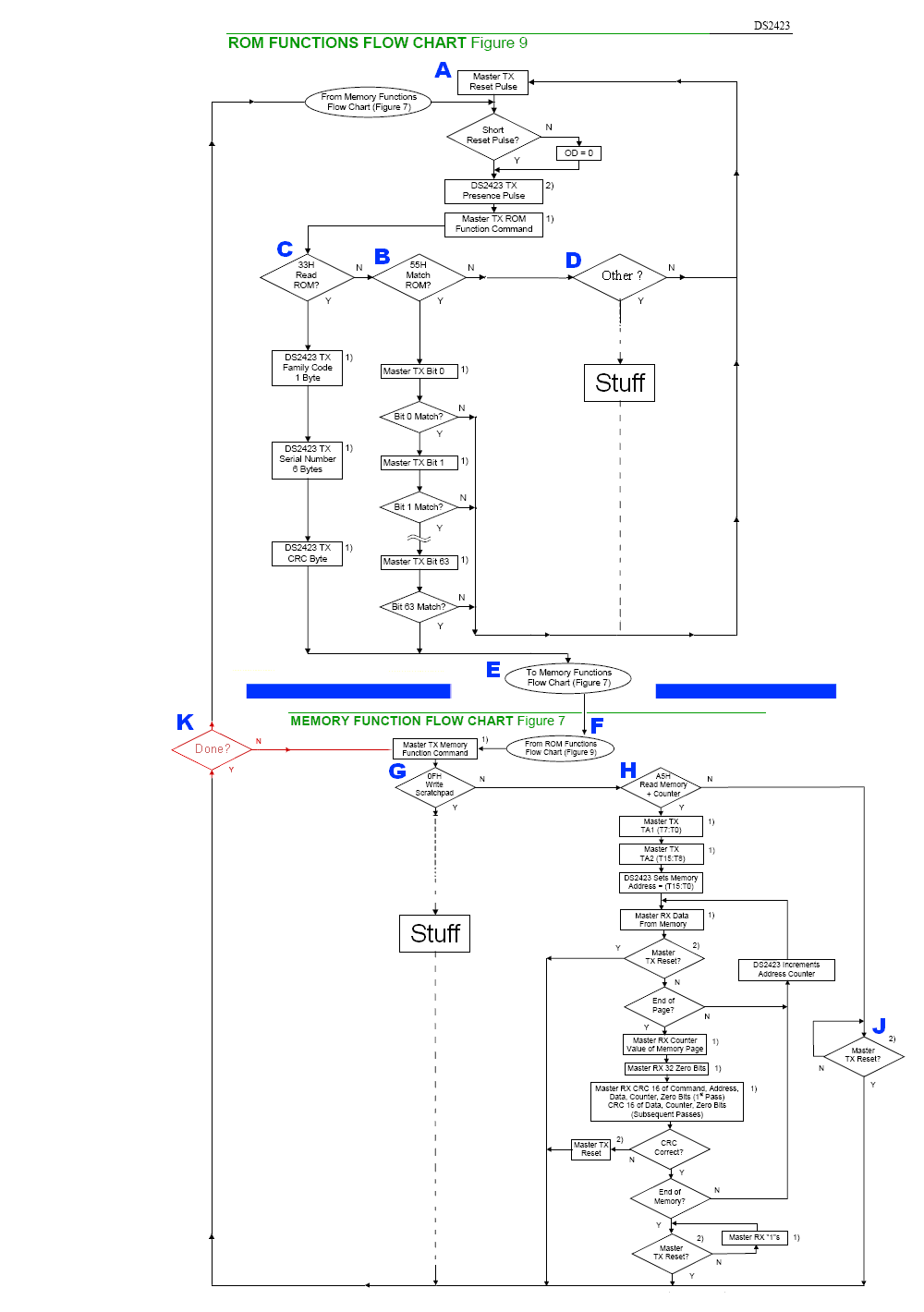
The following is a cut down and merged version of information spread across five diagrams (Figure 9 is in two parts, Figure 7 is in three parts!) in the datasheet.
I hope you've seen flow charts before, but there's an extra twist in this one... it covers things happening in more than one bit of silicon intelligence. For this reason, you have to be very careful to interpret it as the designers intended, which may not be quite how you are used to interpreting flowcharts.
Is is a "choreography" for a rather elegant "dance" between the signals sent by the master through the adapter to DQ, and actions by the attached 1-Wire chips.
Where you see a box, you must often interpret it as a "way station" along the way. "Things" will pause until what is described in the box has happened.
Remember: We are starting from what is either a "quiet time", after a previous successful activity on the MicroLan, or at a time when the master has "given up", and is ready to scrap anything that may currently underway.
So... here's the diagram. I would suggest you print it out, or at least open it in a separate window which you can move to one side on your desktop. The link will open in a separate tab or window, depending on how you have your system configured. With Firefox, if you right-click on the link, you will be offered "Open in new window", among other things.) Don't be overwhelmed by how much is in the diagram.
At the top of the diagram, marked "A" is a box saying "Master TX Reset Pulse". What that means is we start in a waiting mode, We will go on when the master transmits (TX) to the MicroLan a "reset" command, by a "pulse", the pulse being the DQ signal low for a certain period of time, after which DQ will be driven high again by the master. All of the attached 1-Wire chips were "watching" the signal in the "DQ" wire. When it had been low for more than a certain time, the chips knew "Watch out! We're about to start through the big flowchart. Wait for DQ to go high again, and then see what happens next."
If you are using the ultra-simple "one chip per digital input/output mode", then you will skip from the first box, "A", which still works as described above, down to "F", where we begin "talking" to the chip that is the only one hearing things from the master. In the ultra-simple "one chip per digital input/output mode", there is only one chip listening because there is only one chip (per line). In the "normal", "simple" mode, between "A" and "F" we have temporarily "turned off", "sent to sleep", all but one of the chips on the MicroLan.
Returning to the flow chart, just below box "A"....
The reset pulse can be a short reset pulse or a long reset pulse. Even a short reset pulse is long compared with any other period of DQ= low.
You don't have to worry, at this stage, about the pros and cons of short and long reset pulses. In our simple world, we will be using a long reset pulse. That little "OD= 0" thing is not, as is typical for most boxes here, a "wait for..." notation. It merely means "remember that we're going to do things at the regular, not at the "OverDrive" speed.
So we reach "DS2423 TX Presence Pulse". That means that at this point, the DS2423 will transmit (TX) a "Presence Pulse"... i.e. it will "say" "I'm here". It can't be very specific about who "I" is at this point, because all of the 1-Wire chips on the MicroLan will be saying "I'm here." For now, the master only knows that either there are no chips on the MicroLan (no presence pulses seen), or that there is one or more chip present. It can't even tell how many, because two chips may have sent their "I'm here"s at the same moment.
The diagram we are using is adapted from the datasheet for a DS2423. If if were from the datasheet for, say, a DS1820, everything so far would look the same, except the box we've just discussed would say "DS1820 TX Presence Pulse".
Next we come to "Master TX ROM Function Command".
So, things will pause here until the master has transmitted (TX) something. What is a "ROM Function Command"?
Well, at one level, it is simply a number. The master is going to "send" a number out on the MicroLan. All of the attached 1-Wire chips will see it. The "ROM function commands" are common to all of the 1-Wire chips. This part of the flowchart is the same in the data sheet for the DS1820, the DS2438, the DS1920, etc, etc, etc.
The "number", on the flowchart, is either 33H or 55H, which is just a way of saying "fifty five hex". That's sometimes written $55. It is the same as (16 x 5) + 5 in "everyday" numbers. Datasheets often express numbers in hex because sometimes you want to know what that number would be in binary (1s and 0s), and converting from hex to binary is easy. Well. Easier than converting from every day numbers to binary. And you don't often have to worry about it... just so long as in your program you enter the right number. In Delphi, you "make" a number a hex number by putting a dollar sign in front of it.
The flow chart then connects to a bunch of diamonds. Basically this is just a way of guiding you to the information about what happens with the ROM Function Command sent by the master was 33H, 55H, some other numbers, or maybe a number that isn't specifically provided for in the flowchart.
If the program that the master was running called for Rom Function Command 33H to be sent, then you would go down the first path, the one below "C". Actually, this command is rarely of any use. but I left that part of the flowchart in partly by mistake, partly to keep my diagram similar to the original, and to stress the fact that the diagram can "process" many different possible programs.
If the program that the master was running called for Rom Function Command 55H to be sent, then you go down the second path, the one below "B". (In our simple scenario, you will always send a 55H.)
55H, when sent at this point in "the dance" constitutes a "Match ROM" command. The flowchart tells you what happens due to a "Match ROM" command, and I will explain it in a moment, and there is more text about the "Match ROM" command in the datasheet. (As ever, the name didn't help me much in understanding what the command is for, what it does.)
There are a number of other specific codes provided for in the data sheet which we don't need to worry about here. I simplified the general flowchart by replacing their diamonds and paths with the one below "D".
It is possible that the master will have been programmed (by mistake) to transmit a ROM Function Command that the Dallas engineers didn't provide for in the way the chips behave. If that happens, as you can see from the flowchart, the "dance" will loop back to box "A" at the top, and nothing further will happen until the master once more transmits a reset pulse. (Remember: Those boxes usually mean "system stops now until what's in the box has happened.")
But let's say that the command issued was a 55H, which is what is needed if the program is going to accomplish anything. So we start down the path below "B".
55H is the "Match ROM" command. You can read about this command in the text section of the datasheet. I don't like the name, but it is easy to criticize. What will happen between "B" and "E" is that the master will transmit 63 bits. These bits will come from the number that the master was given, the number being the serial number of the 1-Wire chip (they each have a unique serial number "inside" them, remember) that the master wants to stay awake.
Over and over, 64 times, the master transmits a bit (a "1" or a "0", the "digits" of a number when it is written in binary) and inside each chip on the MicroLan a comparison is made between the 1 or 0 just received by the chip and the next bit in the chip's serial number, if that number were written out in binary.
(Yes 64 times, even though the last bit sent is bit number 63. But we sent a "bit 0" at the start, didn't we? Suppose we just sent bits 0,1 and 2? Even though "2" was the last, we've sent 3 bits, haven't we?)
As long as the bit received and the next bit in the chip's serial number match, we go on looking at the incoming bits. If they DON'T match, then the flowchart tells you what the DS2423 we're dealing with will do: It will follow the line back to the top, and wait until the next time the master sends a reset pulse. Do you see what has happened? The chip has seen "Oh... he's not talking to me", and "gone to sleep". We said that this was going to be part of how the system worked, didn't we?
===
But! If all 64 bits sent DO match the 64 bits of the serial number in the chip we are watching, then we are led by the arrows to the lower part of my diagram. In the datasheets, everything below the thick horizontal blue lines is in the various pieces of Figure 7. What happens after you have got this far varies from chip to chip, hence the separate diagram. The stuff above the thick horizontal blue lines is the same in every chip's datasheet. Wow! So much stuff you won't have to read again!
Now, in the lower part of the diagram, we again have some diamonds. Just two, because again I've simplified the diagram. When the master has sent the 64 bits... regardless of what any of the listening chips do... it will then send another number. Well it will, if the program it is running is put together properly. The box just above diamond "G" says that it will.
Again, in our simple case, the number we need to send is A5H. (Yes, "A5H" is a number... I'll explain in a moment.
If the DS2423 receives a A5H at this point, it sees it as a "Read Memory + Counter" command. The flowchart tells you what happens due to a "Read Memory + Counter" command, and I will explain it in a moment, and there is more text about the "Read Memory + Counter" command in the datasheet.
But first, in case you are new to hex numbers, what is this about "A5H" being "a number"??? Start by taking the "H" off the end. That's just to say "treat what comes before this as a hex number." If you write $A5 that, to me, is a clearer way to say "the hex number A5".
But we're still left with a number that has a letter where you'd expect a digit.
Bear with me...
In binary, we count....
000
001
010
011
100
101....
In decimal, our everyday numbers, we count....
000
001
002
003...

008
009
010
011
012
013...

018
019
020
021
022
023...  etc, etc.
In HEX, computer people count....
000
001
002
003
004
005
006
007
008
009
00A
00B
00C
00D
00E
00F
010
011
012
013...

018
019
01A
01B
01C
01D
01E
01F
020
021
022
023... etc.
I hope that has helped... but don't worry overmuch if it hasn't. Just take my word for it: A5H is a number. Hex numbers are made up of characters from the set....
0, 1, ,2 3, 4, 5, 6, 7,
8, 9, A, B, C, D, E, F
... so the following ARE hex numbers, using three ways of saying "hex number"...
$12
$A5
$53FA2
12H
A5H
53FA2H
12h
A5h
53FA2h
Even $53fa2 would be considered a valid hex number, although it is usual to put the A, B, C, D, Es and Fs in upper case. As that is true, it is perhaps wise to use a lower case "h" if you want to use an appended "h" to signify a hex number, as done in the last three examples above.
Something like W5H, or $W5 would NOT be a hex number. The letter must be below G.
Right! Enough about hex!
What happens next, if the master specified the serial number of this chip, and then sent the $A5 command?
Well... things get a bit tedious. Basically, the master sends two more numbers, and then sits back and starts to listen, while the DS2423 spits out a whole bunch of numbers.
In the flowchart, you see....
"Master TX TA1 (T7,T0)", and "Master TX TA0 (T15,T8)", and
I could explain how all of that makes sense, but I'm going to take a shortcut and tell you:
The master will either send $C0 followed by $01, or it will send
$E0 followed by $01.
It will do the first if it wants to know how many times input "A" has gone from high to low, and it will do the second to learn how many times input "B" has gone from high to low.
If you want to know why those numbers, it is explained in the datasheet. For a Read Memory + Counter, those are the only numbers you will ever use, though, so save yourself a headache.
Okay.. now that the DS2423 knows which counter you want to know about, it will start sending stuff.
The flowchart has a box saying "Master RX Data From Memory". (RX: receives.) This box is, I think, a little unhelpful and confusing.
At this point, the master should be watching for data, and that data should be from the memory within the DS2423. The DS2423 should be sending it. But the master has temporarily given "control" to the DS2423. The DS2423 will send the first data byte immediately, whether the master is listening or not! It is a bit like the hoary teacher's lament: "I'm teaching, but is the pupil learning??"
Likewise, the "Master TX Reset?" diamonds in the path labeled "H" are perhaps a little unnecessary. Any 1-Wire chip will ALWAYS stop what it is doing, and go up to the top of the diagram if the master transmits a reset pulse. Perhaps those "Master TX Reset?" diamonds were sprinkled in the flowchart to reassure us that a reset could "break in" on what the DS2423 will do if there is no reset?
So... assuming no reset from the master, what happens?
We'd got as far as "Master RX Data From Memory". We go around a loop...
What's this "page" thing? Well. It is a bit like a page in a book. The memory inside the DS2423 is organized in "pages", In the DS2423, each "page" holds 32 bytes of data. (We know that from the memory map in the datasheet.) The address counter referred to just a moment ago isn't really an address counter, it is an address pointer. We started it off at $01C0 or $01E0, and we fetch data from whatever location the address counter/pointer indicates. AND we SEND it to the master, which isn't stated in the flowchart, but we're meant to infer from the "Master RX data".
And how does the DS2423 "know" that we've reached the end of the "page"? We're at the end of the page when the address counter is 32 more than it was when we started. (The chip probably just counts how many bytes have been fetched, rather than watching for "32 more than where we started", but that isn't what the text of the flowchart implies... though the result is the same, whatever is going on.
BUT WE DON'T CARE what's in the DS2423's memory, in the page starting at $01C0 (called "page 14") or in the page starting at $01E0. We want to know what the counters hold. And they're SEPARATE. But the only way to get them is with the command we are studying now, which STARTS by sending the contents of a page of memory. Sigh.
AFTER the 32 bytes of the page of memory have been transmitted, which the master will watch, but it will throw away the numbers as fast as it reads them, AFTER that, the DS2423 sends four more bytes. This you "know" from the not- very- clear "Master RX (receives) Counter Value of Memory Page". Again, it is really more a matter of the DS2423 TRANSMITTING the data, although one would expect the master would be programmed to "catch" what is being sent. We know that the "Counter Value" consists of 4 bytes only from close study of some stuff in the datasheet... the flowchart really should have told us the "Counter Value" took four bytes, and it should have told us that the bytes were sent LSB (least significant byte) first. This and more is in the text under "Read Memory + Counter [A5H]" in the data sheet. (I wish I'd had the guide you are reading when I was trying to figure all this out. What saved me, sort of, was the "memory function example" in the data sheet... but that takes some "reading" too!)
Then the DS2423 sends 32 zeros. You just program the master to read them and throw them away. (32 bits: 4 bytes). This indicated in flowchart by "Master RX 23 zero bits")
The the DS2423 sends two more bytes. They are a checksum, which, it being 1 am, I am going to skip writing about tonight. (Just program the master to read them and throw them away, if you are feeling lazy. You SHOULD use this checksum, but that will have to be a story for another day.)
The flowchart then has a CRC correct? decision diamond. If you checked the Checksum (you don't have to), and found from it that somehow what the DS2423 read must have been corrupted in transmission, you would at this time ignore the numbers you thought the DS2423 sent, and you would have the master do a reset of the MicroLan, to set things up for another attempt "from the top".
I don't know why the flowchart then has "End of Memory?" next. There's no way to tell if the DS2423 has gone wrong, and if it hasn't, you will have been at the "end of memory" earlier in the flowchart. You won't be going back along the "No" path.
The "Master TX reset?" diamond and "Master RX 1's" at the bottom of the page suggests to me that the DS2423 will now drive DQ high until such time as the master issues a new reset. Remember that the master and the DS2423 are not tightly synchronized. Upon a reset, which will be initiated by the master, when called for by the program running in it, the master assumes control, and all of the 1-Wire chips on the MicroLan go into their "listen for instructions from the master" mode. The master's connection to DQ will be able to pull it high or low. The 1-Wire chips' connections to DQ will allow them to sense its state (and draw power), but they won't drive it high or low. In certain very specific circumstances, the master will "hand DQ over" to one of the 1-Wire chips by, as I said, first telling all the others to "go to sleep", and then issuing a command. When it "hands over", the master will start watching DQ, i.e. it will turn its connection to DQ into an input, and will expect the 1-Wire chip to "drive" DQ for a clearly defined "while"... and then "give DQ back" to the master. And if it fails to do so within the expected time, the program in the master should do a reset, because something has gone wrong, and we need to start again from "square one".
I also had to add a decision diamond which isn't present on the Dallas diagrams. It may not be quite right, especially in respect of those "extra" "Master TX reset" I was just discussing, but what it implies is true:
My extra decision diamond is in red, on the left, labeled "K". It asks "Done?", by which I mean "Are you done with the currently selected chip?" If you aren't it is perfectly acceptable to issue another (or "another another" etc) "Memory Function Command" to the chip, without going all the way to the top of the diagram, resetting everything, re-selecting the chip, etc.
Whew!
One little detail: While I hate to "complain" again, the little loop at "J" seems unnecessary, if you move the arrow at the top of the page, and if you interpret that first "Master TX Reset Pulse" box to mean "We start here, and until this has happened, we don't go on." It probably is necessary, in order to portray what is happening exactly right... but I don't think you'd go wrong with my simpler approach. Ah well.. the whole 1-Wire line is fantastically fun to work with, and the little quibbles I can raise when trying to help a novice get though the datasheet shouldn't put you off!
===
SO! That's what's needed. Now we turn to how we make all of that happen. Happily, we don't have to do anything with or to the DS2423 apart from hooking it up, and providing something to send negative edges to the A and B inputs. ("Negative edge": The going of a digital signal from high to low. As with airplanes having to land once for every time they take off, so you will have a positive edge for every negative edge... but the DS2423 only counts the negative edges.)
But you will have to write the program for the master... and here is were TMEX comes to the rescue. Remember: It is your "translator". You are the President of the United States, and the MicroLan is the President of Mars,.. but you can speak "English" to TMEX, and it will pass on your message to the MicroLan, and pass back things coming from the chips there, e.g. the 4 bytes giving the count in one of the counters.
(Users of microcontrollers may use libraries which take the place of TMEX, not always on a one- to- one relationship between the microcontroller library and the TMEX routines, but however it is done, by the time a signal gets to DQ, all that we've said so far remains valid... remembering that I said that for the ultra-simple "one chip per digital input/output mode" you can skip over part of the things we discussed above.
Alternatively, the user of a microcontroller might "bash" the "bit" connected to DQ directly... but I recommend that you find examples done by someone else, if you want to go down that path!)
The above gives you the fundamentals of how 1-Wire and MicroLans work. In the next essay, I go into how you use TMEX to run MicroLans of 1-Wire chips, i.e. how to achieve all of the wonderful things explained above.
And, as I said elsewhere, I also I have also done for you a separate tutorial with you the full sourcecode for an application to read the counter registers in a DS2423.
I'm sorry, but I'm going to end this somewhat abruptly here (again!), as there's a lot of work to do still to get the text online for you, and I suspect you'd rather I did that than do a flowery "concluding remarks" section?
Another resource...
Long ago, I addressed using the DS2423 once before. I don't think I did nearly as well as the explation above, and in the associated general overview of doing programming for 1-Wire, but if you want to look at another DS2423 reading program, here's a zip with sourcecode for that.
![]() Page WILL BE tested for compliance with INDUSTRY (not MS-only) standards, using the free, publicly accessible validator at validator.w3.org
Page WILL BE tested for compliance with INDUSTRY (not MS-only) standards, using the free, publicly accessible validator at validator.w3.org
....... P a g e . . . E n d s .....