This page is browser friendly, by the way. Make your browser's window less wide than your whole screen and you will find the narrower columns much easier to read.
I'll give you details of what the unit offers in a moment, but just before that: On other pages, I have commended this board to people who want 8 LEDs and 8 simple digital inputs. In other words, for the convenience the shield offers, you could use one for those needs, and just "throw away" the capacitive sensors feature. How to do that is explained later.
At 2/11, for $15 by PayPal you can buy you a kit, and cover p&p to a US destination.
The information here is entirely unofficial. It has not been written by or endorsed by the people who brought us the ArduCapSense shield.
Assembly is quite simple. And when you are done, you will have a shield providing the following. Using a clone with an non-standard footprint, i.e. a ModernDevice RBBB? Don't worry... I'll show you how to interconnect the shield to any Arduino (indeed any microprocessor) in what follows.
What you get, quickly and easily, is...
*** 8 "push buttons" to use as inputs to the Arduino. They use 9 I/O lines, between them. (You don't have to use them all. The "cost" will be one line per button, plus an "overhead" of an additional line. The buttons can be operated through a window pane, which may be useful in some applications.
*** 8 LEDs, for output. Each ties up a single I/O line.
*** In addition, as a little bonus, you get a quick, easy way to feed a small amplifier and speakers with a signal which will produce a noise. It uses one I/O line.
I said "what you get quickly and easily..." Later in this essay I will go into some options which are built into the board to let you get other things from the same lines.
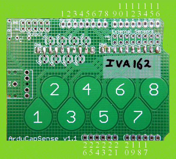
In the course of this essay, I am going to number the pins as follows. Why not just use the silk screened IDs? Just in case a new version comes out with different markings, despite a similar circuit.
I am "naming" the pins with numbers from 1 to 28, clockwise from the board's "upper left". My numbers are shown on the illustration above, and discussed below...
First bank, pins 1-8:
1: Aref
2: Gnd
3: Digital line "13", aka D13
4: D12
5: D11
6: D10
7: D9
8: D8
"Aref" and the "Gnd" signal on pin "2" do not connect to anything on the ArduCapSense board, even though the pins will be connected to things in the underlying Arduino when the ArduCapSense is used as a normal shield. (The ArduCapSense ground trace connects through to the Arduino's ground via pin 25, discussed below.) The other 6 pins are used in the circuits on the ArduCapSense Shield. Details later.
Second bank, pins 9-16:
9:  D7
10: D6
11: D5
12: D4
13: D3
14: D2
15: D1, aka "Rx" as this is the pin set
   up inside the Arduino to send serial
   data from the big PC you use
   to program the Arduino.

16: D0, aka "Tx" as this is the pin set
   up inside the Arduino to receive the
   serial stream from the big PC you use
   to program the Arduino
Pins 15 and 16 do not connect to anything on the ArduCapSense board, even though the pins will be connected to things in the underlying Arduino when the ArduCapSense is used as a normal shield. All of the other 6 are used in the circuits on the ArduCapSense Shield. Details later.
Third bank, pins 17-22
17: A5.. the "Analog5" input. See note below
18: A4
19: A3
20: A2
21: A1
22: A0
All 6 are used in the circuits on the ArduCapSense shield. Details later.
An aside about the Analog lines... we'll finish the tour of pins in a moment....
1) As explained in the Arduino reference, the pin assigned to "Analog input 5" can also be used for digital I/O, exactly as you would use, say, D2, if you reference "D19". At 2/11, the Arduino reference says you can also use "A5", so either of the following would be perfectly acceptable, and equivalent...
The old way...
pinMode(D19, OUTPUT); digitalWrite(D19, HIGH);
The new way...
pinMode(A5, OUTPUT); digitalWrite(A5, HIGH);
Fourth bank, pins 23-28
23: Vin: details follow
24: Gnd: ditto
25: Gnd:
26: 5v: ditto
27: 3.3v: ditto
28: /Rst: ditto
Of pins 23-28, only 25 and 26 connect to anything on the ArduCapSense board. You have to look closely to see this! Don't be fooled! Even though pins 24 and 25 are both labeled "Gnd", only 25 connects to the parts of the ArduCapSense board which should be at zero volts. This includes the fine "screen" of traces, 0.05" apart on both sides of the board.
Pin 26 will normally be the source of 5v for the circuits on the ArduCapSense board, i.e. the designer expects 5v to come into the board over this pin, from the Arduino it is plugged into.
The other pins may well connect to "things" in the Arduino under the shield, but there is no connection between the pin and the circuits on the shield. From this you know that if you are connecting the shield to something which doesn't have the Arduino "footprint", there is no need to connect anything to them. I can think of no application for the shield where you would NOT connect the zero volts from the rest of the system to pin 25, and 5v from somewhere to pin 26.
So now you know what will come into the ArduCapSense shield if you just plug one into a standard Arduino, e.g. a Duemilanove. That information should be sufficient for people wishing to connect the board to other microcontrollers, e.g. the ModernDevice Arduino clone called the RBBB.
The connections you NEED to make are:
0 volts to pin 25, the left hand "GND" 5 volts to pin 26, helpfully labeled "5v"
That's what comes into the board. We'll discuss where each signal goes later. Basically, one (pin 22) goes to the little circuit designed for driving a speaker, probably best done through a simple amplifier. Maybe a piezo device could be driven instead... I'm not sure.
Eight go to turn LEDs on or off... and those lines have some alternative connections into the ArduCapSense shield. (Shield pins 3, 4, 5, 17, 18, 19, 20, 21, by my numbering system given on green photo of board, above.)
Eight go to the 8 pads which act as "buttons"... and those lines have some alternative connections to bring signals into the ArduCapSense shield. (Shield pins 7-14)
One goes to a common "driving" line shared by the "buttons". (Shield pin 6)
One goes a pin which should be configured for output, and takes that output through a resistor and a capacitor to a connector suitable to receive the sort of plug common on MP3 players. The typical use of this would be to plug in a simple amplifier and speaker, and send audio signals out. (Shield pin 22)
(This is a long section. Further down the page I'll turn to using the assembled product, before returning to assembly to do the LEDs, after which I'll explain using them. Using the "output to audio" feature is further down the page, too.
The manufacturer's online guide is GOOD... use it! Read all that is there, and in the "assembly" section here before starting, and consult them as you do the assembly
But in conjunction with those instructions, here are my thoughts.....
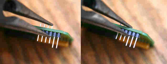
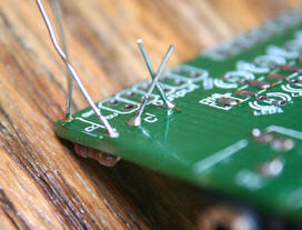
Note what is said about keeping the connections near the "teardrop" pads flush on the "teardrop" side of the board.
Start by installing the two resistor networks, and Get It Right.
Not hard to do.. but easy to get wrong... only one of 8 combinations of following will do... and you are very unlikely to successfully remove a incorrectly soldered array.
Do not rely on the colors in the photo... your components may be differently colored!
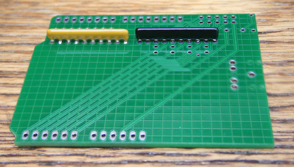
They must be...
  -- on the correct side of the board
  -- with the correct array in each position
  -- "turned" the right way
In order to leave the "teardrop" side as smooth as possible, either solder the arrays in with the ends of the pins even with the surface of the board... easy but not a great idea... or carefully bend the tip of each pin flat before soldering it... not as hard as it sounds. But be careful the bent down end- of- pin doesn't extend beyond the pad it is soldered to. It is also a Good Idea to insert the pins as fully as possible, to leave the resistor array up tight against the PCB... but this will mean you need to carefully trim the pin lengths. (Actually... if you look closely at a drawing of the board layout (provide one), you will see that if you are careful about which WAY you bend each end- of- pin, in ALMOST every case, it won't matter if the pin end goes past the pin's pad....
RNL: Bend each pin above or below an LED's position toward the LED. Take care with the other two.
RNC: With the board turned to put the "External sensors" pads at the "upper right"... Take care with the left-hand-most two pins. Bend the others "up" (towards the "External sensors" pads.) You may want to leave this component out if you are not using the capacitive sensors feature of the board... but I don't think you need too, and it won't be easy to fit later. Think carefully about your needs. In many cases, the presence of RNC won't interfere, even if you are only (for now!) interested in the easy connection of external digital inputs over the lines the 10 meg resistors in RNC connects to.
Or, you can just get on with it, not fuss... as long as you put the correct array in the correct position, on the correct side of the board (NOT the "teardrops" side), and "turned" correctly.
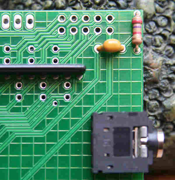
Install the three components of the audio output line option: The resistor, capacitor and connector.
Be sure to put them on the correct side of the board.
The resistor and capacitor are not polarized... you can install them either way "around". It won't matter if the ends of the pins project slightly from the "teardrops" side of the board, so go ahead and solder the resistor and capacitor in "normally".
(before trimmed)
(trimmed)
The pins of the connector should not protrude badly on the "teardrop" side, but the connector should be tight against the PCB. Also: No adjacent pins of the connector should be shorted. With intelligent bending of the pins (up or down, left or right), you can achieve all of the above. Bend them flat before you try to solder them. I relied on the green coating to insulate the "too long" pin ends from the fine mesh of crisscrossing tracks on the "teardrop" side of the board, and seemed to get away with it.
Now install the pins that make the PCB a shield. Even if you aren't using it that way, the pins will be useful as you can plug them into breadboards.
Solder the 0.1" rows of inter PCB pins in place. The upper rows can be soldered "normally". The ones just below the 5 and 7 teardrops should be soldered so that the pins protrude as little as possible above the "teardrop" side of the board.
Careful work with some needle nose pliers will push the pins through the plastic block that ties them together. If you find this easy, it would be as well to do it to all 28 of the pins which "marry" the shield to the Arduino beneath it... but if you had trouble, it is only "essential" for the 12 pins just below the 5 and the 7.
During the soldering of each strip of pins, start by soldering a middle pin into the board. Then check, and if necessary adjust, the angle of the pins to the board until they are perpendicular to it. (Don't bent the pin... re-melt the solder, re-position the pins while it re-freezes.) Then solder the odd numbered pins, then the even numbered pins. (The odd- then- even trick minimizes the heat build up in any portion of the strip of pins during the process.)
You're "done"! For now. Play with the shield some before installing the LEDs or header pins for the External Sensors or Output connectors. NOTA BENE: When you come to install all of those things, they go on the OTHER side of the board, on the "teardrops" side. And, good news: For all of those components, you can use normal soldering techniques, the solder side doesn't have to be smooth and flush.
We're now ready to see the "buttons" in action. (When we turn to driving the LEDs, later, that is MUCH easier!)
Either plug the shield into an Arduino, "piggy-back", or connect...
From Arduino  To ArduCapSense
clone...      pin...

0 volts       25
5 volts       26
Then connect individual digital I/O pins from your Arduino to the ArduCapSense lines in the right hand column below. If you use the Arduino lines indicated, your system will run programs designed for the shield in an Arduino... but you don't have to use the same mapping... just connect one digital I/O pin to each "button pin" from the ArduCapSense.
From Arduino  To ArduCapSense
clone...      pin...

D9       7
D8       8
D7       9
D6      10
D5      11
D4      12
D3      13
D2      14
AND, whether you want to use one or eight buttons...
D10 6
I am only a "one eyed king" when it comes to reading the buttons. The essay by Paul Badger on capacitive sensing at the Arduino Playground will tell you "all about" setting up to read the buttons. In a (poached) nutshell...
Install the CapSense library on the big computer you use for writing Arduino programs, and feeding them to your Arduino. If you are new to "libraries", I have a tutorial about what libraries are, how to use them.
The CapSense library can be downloaded from the main Arduino site.
Now... I couldn't EXACTLY apply the advice in my tutorials on libraries (as it stood when I wrote that!
1) I am now using version 0017 of the Arduino development environment. It puts libraries in...
C:\Program Files\arduino-0017\hardware\libraries
(There's also a...
C:\Program Files\arduino-0017\lib
... to tempt you... but it doesn't have any of the standard libraries you would expect to see- EEPROM, Firmata, Servo, etc.)
AND, CapacitveSense003.zip was more complicated that the last library I installed.
To give my system the CapSense library, I just created, by hand...
C:\Program Files\arduino-0017\hardware\libraries\CapSense
... and dragged into it...
CapSense.h
... and...
CapSense.cpp
...from the .zip.
I closed and reopened my Arduino development environment. (Didn't re-boot the computer).
FOR THIS QUICK TEST, I connected, only,....
From Arduino  To ArduCapSense
clone...      pin...

0 volts       25
5 volts       26

D3      13 .. should enable button "7"
D2      14 .. should enable button "8"

AND

D5      6 .. this is the "common" driver line for the CapSense software.
I then entered the following, which is only a light adaptation (pin numbers, in particular) of the example at the Playground...
(This code HAS actually been tested!)(As opposed to the untested LED demo given below.)
//CapSen1
//ver 2 Mar 11, 20:20
//Created from online demo 2 Mar 11, 20:20
//Demo: At....
//http://www.arduino.cc/playground/Main/CapSense

#include <CapSense.h>

/*
 ** Slight adaptation, for <ref> of...

 * CapitiveSense Library Demo Sketch
 * Paul Badger 2008

 ** Demo being used with ArduCapSense shield... ArduCapSense.com,
 ** connected to an RBBB- see pin numbering
    guide elsewhere in essay this comes from
    for shield pin numbers.
 (Shield pin numbering starts at upper left,
    at "Aref", as "1", proceeds around board
    clockwise.)

 Arduino  Shield
 0v    CORRECT "gnd" pin: 25...only that one is "good"
 5v    5v: pin 26
 D10   Pin 6: The pin the shield would connect to
          if plugged into an Arduino
 D2    Pin 14: ditto
 D3    Pin 13: ditto


 */

CapSense   cs_10_3 = CapSense(10,3);        // 10 meg ohm resistor between pins 10 & 3, pin 3 is to "7 button"
CapSense   cs_10_2 = CapSense(10,2);        // 10 meg ohm resistor between pins 10 & 2, pin 2 is to "8 button"

//cs_10_3, cs_10_2 are "arbitrary" names... you could use "Peg" and "Fred", as long as you substituted 1:1 throughout the
//program. Hopefully you can work out for yourself how these objects got the names they were given.

void setup()
{

   cs_10_3.set_CS_AutocaL_Millis(0xFFFFFFFF);     // turn off autocalibrate on first channel - just as an example
   Serial.begin(9600);
   Serial.println("Time since last, reading on first line, reading on second.");
   Serial.println();
}

void loop()
{
    long start = millis();
    long total1 =  cs_10_3.capSense(30);
    long total2 =  cs_10_2.capSense(30);

    Serial.print(millis() - start);        // check on performance in milliseconds
    Serial.print("\t");                    // tab character for debug window spacing

    Serial.print(total1);                  // print sensor output 1
    Serial.print("\t");
    Serial.println(total2);

    delay(10);                             // arbitrary delay to avoid overwhelming serial port
}
When I ran the above, I got a stream of numbers on the serial monitor. If you numbers aren't quite the same, don't be alarmed...
20	187	80
20	215	49
20	246	77
21	268	50
21	209	64
22	612	233...
etc.
When I touched a finger tip carefully JUST to the "7" "button", the numbers became...
30	2792	465
35	4588	566
38	5273	565
37	5118	588
38	5226	582
38	5258	591... etc...
When I touched the "8" pad, I got...
26	390	1789
30	623	2664
32	598	3263
34	745	4074
36	668	4546
37	732	4744
39	736	5348
39	791	5461
40	749	5741
35	837	3994... etc.
If you get -1 or -2 in the second or third column... in which case the stream of numbers may be generated quite slowly... about 3 seconds per line... you are getting error messages from your call of the central capSense() routine. See the Playground article on the CapSense library for details.
So! There you have it! Two working "buttons"/ Extending the above for all 8 is left as an exercise for the student! Note that if you connect the shield as a shield, you will use different numbers than I have used in the example program.
(Remind me to edit this, give you some help!)
Whew! What comes next is easier!
When you are ready to install the LEDs, you can just get on with it, or you can follow my perhaps OCD procedure, outlined below. Whatever you do, be sure to install each LED the "right way around." They are polarized devices, but if you put one in "backwards" it will simply not work until turned around. No harm will be done.
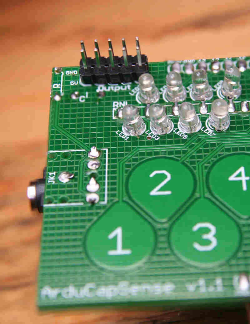
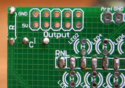
The LEDs are simple, and entirely separate from the "buttons". (Note also in the photo the correct side of the board for the "Output" connector pins. Install it later. The connector pins for the External Sensors go on the same side.)
Remove the shield from any Arduino you may have had it connected to. While I have described the process as "dry fit all LEDs, test, solder one of each, test further, solder other...", it may work better to do the following....
"Repeat 8 times: Insert one, dry test. Solder one leg and trim Until all 8 in, right way 'round, one leg soldered. ... then... re-test, align LEDs, solder and trim other legs."
Your choice!
Just for this section about getting the LEDs installed correctly, I'm going to introduce a new pin reference scheme. In this section pin names, assigned from upper left, clockwise are in four blocks, i.e...
A     B
123.. 123..

     D       C
...321  ...321
In other words, the pin "names" I assigned earlier map onto the "new" names as follows....
Old  New

1    A1
2    A2
3    A3
4    A4
5    A5
6    A6
7    A7
8    A8
9    B1
10   B2
11   B3
etc.
I will refer to the LEDs by the red numbers in the following diagram...
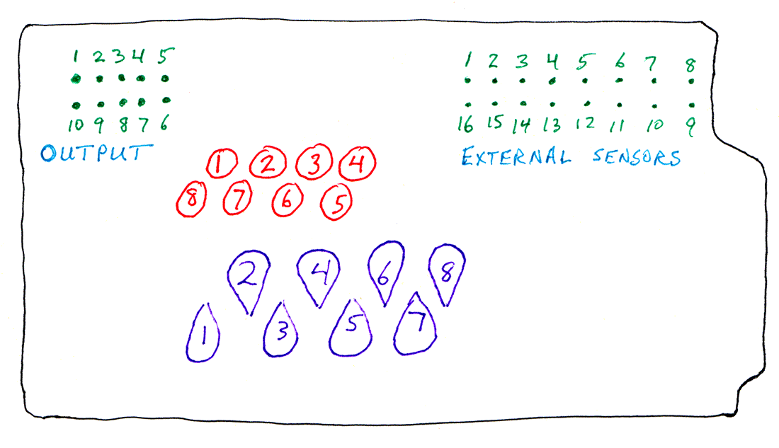
Note that this differs from the numbering scheme in the PCB's silkscreen, at least in the version 1.1 boards... sorry! (We will use that diagram several times in the following.
Insert, but do not solder, all of the LEDs. The short leg always goes nearest the resistor array. Bend the legs slightly to keep them from falling out. Try to bend them so that the four in each group are not touching any from any other group. ("Four groups": The upper legs of the four upper LEDs, the lower legs of upper LEDs, upper legs of lower row, and lower legs of the lower row.)
Connect 0 volts to pin D3.
Connect 5 volts... briefly!... to pin C4. LED 8 should light up. Don't be alarmed if it doesn't... or if extra ones light. Are there short circuits between the as- yet- untrimmed legs from the LEDs? Are the legs of the LED actually touching the sides of the holes they pass through? (Wiggle the). Eventually you should get it to light... IF you have inserted it the right way around... short leg towards the resistor network, remember. If all else fails, try the LED the other way around. It won't hurt anything if it is in "backwards"... but it won't work, either. Another way for this test to fail is if there is resistance between C4 and the left hand end of the resistor network, the pin marked RNL.
Anyway! Having got LED 1 to wink briefly, repeat the exercise with the other ones. In every case, you leave zero volts connected to C3.
If more than one LED winks, you probably have a short between the untrimmed legs. Adjust. Try again.
5v to... LED that lights...

(C4  LED 8)
 C3  LED 7
 C2  LED 6
 C1  LED 5

 C5  LED 1
 A3  LED 2
 A4  LED 3
 A5  LED 4
(When two of the pins for the 5v connection are adjacent, it is perfectly acceptable to connect the 5v with a crocodile clip "pinched" across the two of them... and then both LEDs should light... if you wiggle the leads... and you can see if they are nicely aligned.)
Once you've got each LED to blink, on it's own, solder ONE leg of each LED in place, and trim that leg. Recall that it doesn't have to be trimmed flush, and probably shouldn't be.
Now go through the LEDs again, adjusting them minutely so that if all 8 are on, the result will be pleasing. If the LEDs point slightly different directions, the result will not be so pleasing. Solder and trim other leg as you go along.
Now that the LEDs are installed, you can do some new things with your shield.
Either plug it into an Arduino, as a shield, or connect...
From Arduino  To ArduCapSense
clone...      pin...

0 volts       25
5 volts       26
Then connect individual digital I/O pins from your Arduino to the ArduCapSense lines in the right hand column below. If you use the Arduino lines indicated, your system will run programs designed for the shield in an Arduino... but you don't have to use the same mapping... just connect one digital I/O pin to each LED line that you wish to use. "Digital I/O pin"? but you are connecting LEDs to analog lines of the Arduino! Yes. That's allowed. You can use an "analog" input pin for digital I/O, as explained in the Arduino reference.
D13   3
D12   4
D11   5
A5   17
A4   18
A3   19
A2   20
A1   21
Here's a really simple little sketch (untested) to wink each LED separately, one after the other. The sequence may need work. It's not the most elegant program I ever wrote, but it shouldn't be too hard to follow!
If someone would be kind enough to tinker with this, and fix it so that the LEDs light one after the other, from (my) "1", to 2, to 3, I'd be grateful. The only part of what follows which should need changing is the "const byte LED0 13;", etc. lines. Please leave them in the order LED0, LED1, LED2, etc. You may have to change the 13, 12, 11... pin assignments.
//WinkEm

const byte LED0 13;//NOW I start "counting from zero"!
//Most of this essay starts countings at "1"
const byte LED1 12;
const byte LED2 11;
const byte LED3 16;//Another way to refer to A0
const byte LED4 17;
const byte LED5 18;
const byte LED6 19;
const byte LED7 20;


setup()
{
pinMode(LED0,OUTPUT);
pinMode(LED1,OUTPUT);
pinMode(LED2,OUTPUT);
pinMode(LED3,OUTPUT);
pinMode(LED4,OUTPUT);
pinMode(LED5,OUTPUT);
pinMode(LED6,OUTPUT);
pinMode(LED7,OUTPUT);

digitalWrite(LED0,LOW);//Turns LED off
digitalWrite(LED1,LOW);
digitalWrite(LED2,LOW);
digitalWrite(LED3,LOW);
digitalWrite(LED4,LOW);
digitalWrite(LED5,LOW);
digitalWrite(LED6,LOW);
digitalWrite(LED7,LOW);

}

loop()
{
digitalWrite(LED0,HIGH);//Turns LED on
delay(120);
digitalWrite(LED0,LOW);
delay(120);

digitalWrite(LED1,HIGH);
delay(120);
digitalWrite(LED1,LOW);
delay(120);

digitalWrite(LED2,HIGH);
delay(120);
digitalWrite(LED2,LOW);
delay(120);

digitalWrite(LED3,HIGH);
delay(120);
digitalWrite(LED3,LOW);
delay(120);

digitalWrite(LED4,HIGH);
delay(120);
digitalWrite(LED4,LOW);
delay(120);

digitalWrite(LED5,HIGH);
delay(120);
digitalWrite(LED5,LOW);
delay(120);

digitalWrite(LED6,HIGH);
delay(120);
digitalWrite(LED6,LOW);
delay(120);

digitalWrite(LED7,HIGH);
delay(120);
digitalWrite(LED7,LOW);
delay(120);
}
STILL TO BE FINISHED: Driving audio...
Preliminary "guide": Shield pin 22 (using my original numbering scheme, not the one peculiar to the LEDs section of this) routes A0, which can be used for digital output (see above), to a resistor which goes to a capacitor, which goes to a connector for the sort of plug common on earphones for MP3 players.
If you set A0 up for output, and send a squarewave of about 260 Hz to the output, and plug an inexpensive amplifier and speakers (the sort used to "play" sounds from a computer) into the connector, you should hear a tone nearly the pitch of middle C (C4) on a piano.
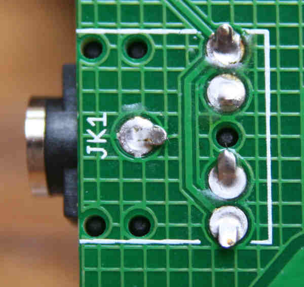
When you insert a plug into the connector at "J1" (the only MP3-player-type plug on the board), you will connect the shaft to the shield's "ground" (i.e. zero volt line), and at least one... both I think... of the other parts of the plug (tip, and middle collar for stereo plug, just tip for mono) to the line passing to the resistor and capacitor on the shield, and, ultimately to Pin 22, A0 when the shield is in an Arduino.
In the diagram I gave earlier (opens in new window or tab), when I started on the LEDs, you should also see two blocks of pins drawn in green, labeled in cyan: "Output" and "External Sensors".
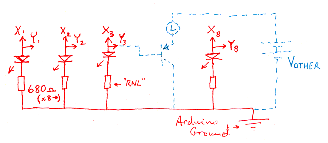
The block of pins marked "Outputs" has the following:
You need to be careful not to draw too much current out of the shield via these connections... there is a "per pin" limit, and a "total for all pins" limit. But with care, you can, say, drive (probably through a transistor or other means) an electromechanical strikeplate (as part of a door lock) by one of the digital I/O lines, and have a LED show you when the strikeplate is energized.
In the following, the "1", "2"... "8" are only to "group" things... they don't relate to the other 1s and 2s, etc, in this essay.
The battery (Vother), load and transistor shown in dotted cyan suggest one external circuit you might choose to connect through the "Outputs" pins.
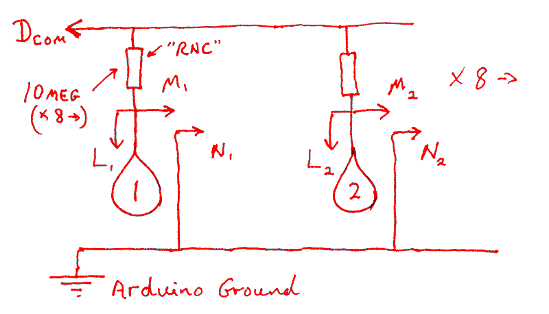
The block of pins marked "External Sensors" in the upper right of the board are, I believe... still need to test this!... a way for you to provide a supplemental set of capacitive sensor pads which your Arduino will "watch". For each channel, there is a pin for the sensor (bottom row) and a pin to connect to the shield's ground (0 volt line). The pads on the PCB are, of course, easy to use and convenient... but if you want to create a different set of pads, it should be easy.
From looking at the circuit diagram, it seems to me that you could also connect a simple switch between any of the external input pins (bottom row in header) and one of the pins from the upper row. (They all connect to the shield's ground", or "0 volt" line.) If you did this, you would sense the switch as open or closed with a simple digitalRead of the relevant line. You would, when the switch was closed, be connecting the CapSense "driving" output of your Arduino (typically D10) to ground, through a 10 meg resistor. This might affect the behavior of one or more of the cap sense pads... I'm not sure. I'll try to explore all of this one day. Also, there may be other "details" to attend to... so I will try to expand this section later.
I think the following tells you about...
(A quick note on how the capacitive sensors work: Dcom connects to an output from the Arduino. When it changes state, the states of the "L" lines... inputs to the Arduino... change shortly after. How long it takes them to follow Dcom is determined by what is near the relevant pad.
... but I'm not sure the circuit or my comments are entirely right! Use with caution!
If I have things right, then one of the reasons for the "External Sensors" header pins is to allow you to connect either of the following to one or more of the channels feeding a signal to the Arduino....
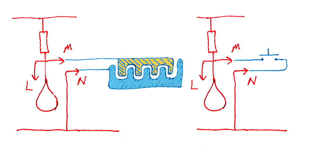
Besides the convenience of having the sensor pads in a different place, physically, than on the surface of the shield, there may be times when pads of different dimensions, arranged differently would be preferable. I am sure that there are various design trade-offs open to you when you start making your own pads... some designs will be simple, some will offer enhanced sensitivity and reliability, etc, etc.
The second "circuit", the simple switch, shows you how little you need to add if you merely want to use a channel to read a digital input.
Please remember that the information here is entirely unofficial. It has not been written by or endorsed by the people who brought us the ArduCapSense shield.
![]() Page tested for compliance with INDUSTRY (not MS-only) standards, using the free, publicly accessible validator at validator.w3.org
Page tested for compliance with INDUSTRY (not MS-only) standards, using the free, publicly accessible validator at validator.w3.org
CSS behind the page checked, at least once upon a time!, with http://jigsaw.w3.org/css-validator/
Why does this page cause a script to run? Because of the Google panels, and the code for the search button. Also, I have some of my pages' traffic monitored for me by eXTReMe tracker. They offer a free tracker. If you want to try one, check out their site. Why do I mention the script? Be sure you know all you need to about spyware.
....... P a g e . . . E n d s .....