Before we get too far into this... is it a servo "motor" that you want for your job, I hope? I offer a more general discussion of things to turn electricity into movement, in case you are in any doubt. As is explained more fully there, a servo, at least as I am using the term here, is a device with an arm that rotates on a shaft... like a robust "hand" on a clock. It can more "forward" or "backward", often through most of 360 degrees. Note that I am not aware of any servos that can go "round and round".. all of the servos I am aware of are limited to only part of a full circle's rotation.
The input to the device is a single wire. You put a stream of ons and offs into that wire. (A pulse train If you have short ons, with long offs, the "hand" is rotated to one position. If you have a different duty cycle (ratio of the on time to the off time), the "hand" goes to a different position.
So! Pretty simple! And that, happily, means that using them is also pretty simple... especially as Arduinos can be told to send a pulse train without the need for every detail to be managed by your code.
The "big secret", such as it is, is that you are not free to put servos on whatever pin you wish to. Only some have the capacity of delivering a pulse train for you.
To "crawl" before we "walk", here's the core of the code we'll come to in a moment. The following is the heart of just moving one servo's arm to a position. (Change the "85", and the code would move the arm to a different position.)
The #Include <Servo.h> allows the compiler to draw onm material in the standard "Servo" library. It takes care of tedious details for us, and is an "everyday" library... nothing you need to worry about.
#include <Servo.h>
Servo dog; // "Dog" being the "name" of the servo

**const uint8_t servoMax = 1; // Change to suit the number of servos used (max 6)
**uint8_t oldPos[servoMax];
**uint8_t newPos[servoMax];

// **********************************************************************
void setup() {
  //Configure the Arduino to "drive" the servo via pin 9...
  dog.attach(9); // Available pins for the Uno are 3,5,6,9,10,11 (PWM pins)
}

// **********************************************************************
void loop() {
dog.write(85);
}
I've put the "write" in the loop() part of the program in the "cut-down" version, but once that had been executed once, you wouldn't see anything new happen thereafter.
=============
Here's a program that a reader kindly sent for everyone's benefit. It goes a bit beyond the basic basics... It illustrates how you would drive three servos from an Arduino! But the code is nice and clear, and I hope you can take useful things from it. More importantly, it gives you an elegant way to control how quickly the arm moves from one position to another. To "exercise" the servos, author of the program added three potentiometers, which are only there to give the user an easy way to say "Now I want (that) servo to change the direction it's arm points to (this new direction).
The "timing" issues discussed in the comments within the full code are NOT about what the duty cycle will be. The (standard, widely used) "Servo" library takes care of that nuisance.
And... not least... he's used the millis() function in a clever way to frequently re-check the position of the pots, so that the signal to the servos can be changed if necessary... but in a tidy, un-wasteful, non blocking way.!
Lastly: If you haven't met "map" before, it is worth getting to grips with... a generally useful word, nothing connects it directly to servos... it was just "the way to go" here, for converting a reading from the pot to a range of values suitable for the servo.
/*
  Using servo motors at various speeds without delay
  Every 'interval' milliSeconds, we check to see if the servo needs moving
  We then call the relevent subroutine to move the servo 1 degree
  in the correct direction.
  This repeats every 'interval' until we reach the new position
*/

#include <Servo.h>
Servo dog; // Name these as preferred
Servo cat;
Servo mouse;

long previousMillis = 0;
long ramp = 25; // Sets the speed of the servos
                // (good values are 5 [fast] to 50mS [very slow])

const uint8_t servoMax = 3; // Change to suit the number of servos used (max 6)
uint8_t oldPos[servoMax];
uint8_t newPos[servoMax];

// **********************************************************************
void setup() {
  dog.attach(9); // Available pins for the Uno are 3,5,6,9,10,11 (PWM pins)
  cat.attach(10);
  mouse.attach(11);
}

// **********************************************************************
void loop() {
  /*
     Example using pots to position the servos
     The newPos variable can be set by any other means
     Connect the analog inputs to GND if not used
     This will prevent channel crosstalk.
  */
  newPos[0] = map(analogRead(1), 0, 1023, 0, 180);
  newPos[1] = map(analogRead(2), 0, 1023, 0, 180);
  newPos[2] = map(analogRead(3), 0, 1023, 0, 180);
  unsigned long currentMillis = millis();
  if (currentMillis - previousMillis > ramp) {
    previousMillis = currentMillis;
    if (newPos[0] != oldPos[0]) servo0Move();
    if (newPos[1] != oldPos[1]) servo1Move();
    if (newPos[2] != oldPos[2]) servo2Move();
  }
}

// **********************************************************************
void servo0Move() {
  if (newPos[0] > oldPos[0]) {
    dog.write(oldPos[0] + 1);
    oldPos[0] ++;
  }
  if (newPos[0] < oldPos[0]) {
    dog.write(oldPos[0] - 1);
    oldPos[0] --;
  }
}

// **********************************************************************
void servo1Move() {
  if (newPos[1] > oldPos[1]) {
    cat.write(oldPos[1] + 1);
    oldPos[1] ++;
  }
  if (newPos[1] < oldPos[1]) {
    cat.write(oldPos[1] - 1);
    oldPos[1] --;
  }
}

// **********************************************************************
void servo2Move() {
  if (newPos[2] > oldPos[2]) {
    mouse.write(oldPos[2] + 1);
    oldPos[2] ++;
  }
  if (newPos[2] < oldPos[2]) {
    mouse.write(oldPos[2] - 1);
    oldPos[2] --;
  }
}
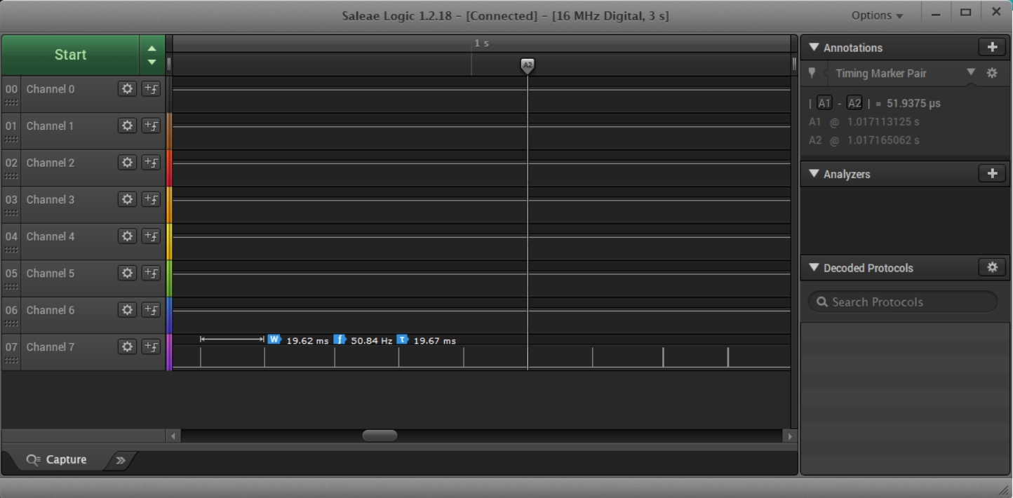
... and here are some data from a slightly modified version of the above...
To quote the person who did this for us... "I did some timing measurements to satisfy my curiosity. The repeat rate is set to 20mS. From the display above, we can see that the time taken in the servo-n-Move() routine is 52uS."
He was using a 16MHz Arduino Mega, and furtehr rremarks: "I have software timers set up like industrial PLC timers (actual, preset and control registers). I then check the status of the timers in the interrupt routine (checked at 52uS), and set a flag to take appropriate actions inside the loop routine."
And... "By the way, I think I may be wrong about the number of servos. I got that information from the net. I was reading the servo.cpp file and that says 12 servos. It seems you can attach any pin to it. More checking required. Also, do not try to use servo.write within an interrupt routine as the servo library also uses interrupts."
To save you looking it up, the gorgeous logic analyser costs over $250. But if you want to give me one, I won't complain. Remember: The program, AND the timings data came from a kind reader.
For the Sparkfun ESP8266 Thing Dev, I found that pins 2, 5 and 13 worked. Others may work, too... but I am pretty sure that the number that will is limited... the pin has to have PWM generation functionality. Pins that did not work for me: 4, 14, A0.
Here's some code I wrote... don't blame the author of the above for anything in this...
//ESP8266Thing-Servo-basic
//Written with Arduino IDE 1.8.1
//Put in a Sparkfun ESP8266 "Thing Dev" (WRL-13711)
//Started 16 Mar 19

#define sPrgm "ESP8266Thing-Servo-basic" //no ; here
#define sVers "16Mar19"

//MOSTLY "works"... just once in a while, especially when starting
//  up, the movement is hesitant. This may be due to running it on
//  3v3. I hope that's all it is!

//Successfully used "Micro Servo 9g / SG90" using the 3v3 from the ESP8266,
//  and 3v3 PWM signal.

//Thanks to ...
//https://circuits4you.com/2019/01/12/esp8266-servo-motor-control/
//.. for much of what is here.

#include <Servo.h>/(Ordinary one)

//"#define ServoPin 14   //D5 is GPIO14" << Didn't work, despite being pp
//https://circuits4you.com/2019/01/12/esp8266-servo-motor-control/
//#define ServoPin D5 //Wouldn't compile
//Also did not work: 14, A0,
//#define ServoPin 2 //Worked!
//Also worked: 5,13 //(5 has on-board LED on it.
//           13 needed for SPI if you want to use that.
#define ServoPin 2// no ; here

Servo MyServo;  // create servo object to control a servo

void setup() {
  delay(500);
  Serial.begin(19200);
  delay(200);
  Serial.println();
  Serial.println("Welcome to servo motor on Sparkfun ESP8266 Dev Thing demo.");
  Serial.println("Program name: ");
  Serial.print(sPrgm);
  Serial.print(", version: ");
  Serial.println(sVers);
  Serial.println();

  MyServo.attach(ServoPin); // attaches the servo
    delay(200);//without this, the servo sometimes
  //"stutters" a bit before it "gets going" with
  //what loop() tells it to do. Only briefly.
  //This only tested on 3v3 so far. Stutter may
  //disappear on 5v Vcc and data to servo.
}

void loop() {
  // put your main code here, to run repeatedly:
MyServo.write(10);   // tell servo to go to position
  delay(800);
MyServo.write(50);   // tell servo to go to position
  delay(800);
  }
If you visit 1&1's site from here, it helps me. They host my website, and I wouldn't put this link up for them if I wasn't happy with their service.
Click here to visit editor's Sheepdog Software freeware, shareware pages.. Material on this page © TK Boyd 3/19
Click here to visit the homepage of my biggest site.
Click here to visit the homepage of Sheepdogsoftware.co.uk. Apologies if the "?FrmAht" I added to that link causes your browser problems. Please let me know, if so?
![]() Page has been tested for compliance with INDUSTRY (not MS-only) standards, using the free, publicly accessible validator at validator.w3.org. Mostly passes.
Page has been tested for compliance with INDUSTRY (not MS-only) standards, using the free, publicly accessible validator at validator.w3.org. Mostly passes.
AND passes...

....... P a g e . . . E n d s .....