This page covers the simple case of driving LEDs directly with Arduino pins. The same information would be helpful to users of PICs and other sources of digital output lines. It does not go into the more interesting matter of multiplexed LEDs.
The following shows you how to connect an LED to an Arduino....
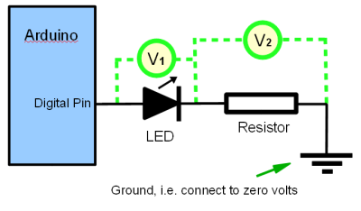
Don't (yet!) worry about the dotted lines or the circles with V in them.
You connect an LED as shown in the diagram: From Arduino digital pin to one leg of LED. From other leg of LED to one leg of resistor. From other leg of resistor to "ground", i.e. to the "negative", or "zero" side of power supply on your Arduino. (One of it's pins is marked "0" or "ground" or "gnd", depending on which board you have.)
Easy! (When you know how)
First of all: Power: the normal 1/4 watt resistor is more than enough, as far as that parameter is concerned. Eighth watt would be okay too, but they tend to be a bit fragile physically.
Second: What value, how many ohms?
I generally use between 330 and 680 ohms. Too big a resistor and the LED just won't glow at all. Nearly too big and it is dim. Too small and either you will burn out the LED, or worse, your Arduino, or at least the circuits of one pin of it. Also, be advised: Different colors and designs of LEDs need different resistances.
So... let's be a little more rigorous about what is "right".
You should not let more than 40mA flow through any of your Arduino's digital or analog signal pins.
And although I haven't found the figure yet, I suspect there's a limit for the device overall. In other words, it would probably be a Bad Idea to have all 20 pins operating at 40mA all at the same time. for a total of 800mA. (20? The 14 "digital" pins, plus the 6 that are normally for analog or PWM work, but can be used as digital pins, if you wish to use them that way.)
When you've set one of the pins up as an output, and set it "high" (we'll go into the details later), it is almost as if the pin is connected to the 5v side of your power supply. So, if in doubt, connect what you are going to connect to a pin to 5v and see how it behaves. If something is wrong, your Arduino won't be involved!
You probably heard of Mr. Ohms' law? From that, we would conclude that the smallest safe resistor would be 125 ohms.... and indeed if your resistor was 125 ohms, the 40mA wouldn't be exceeded. However, the LED introduces a "resistance" (of sorts), so in fact, you could use an even smaller resistor if you wanted 40mA flowing through the LED. Most LEDs achieve their maximum brightness before 40mA, and I wouldn't be surprised if some burned out if that much current flowed through them.
If you know the "correct" current for your LED, you go about working out the value for the resistor as follows.....
Besides giving you the "correct" current for your LED, the specs will also (or you can figure out... that's coming) the "voltage drop" that the LED causes. LEDs do not behave like resistors. Regardless, within reason, of the current flowing through them, they cause the voltage to lessen by a constant amount. (With resistors, as Mr. Ohm noted, the more current there is, the more the voltage lessens, or "drops".)
This brings us to the dotted lines on the diagram above. They, and the circles with "V"s represent voltmeters optionally attached to the circuit. When the voltmeter's leads are attached either side of the LED, as show for "V1" in the diagram, within the normal operating range of the LED, the voltmeter will read the same amount, regardless of the current. the green LED I have on my Arduino at the moment gives rise to a 1.8v drop. The rest of the voltage coming from the pin will drop across the resistor, so V2 "should" read 3.2, if the pin is delivering a full 5v. In actual fact it may be a little less than that... but if I do my calculation based on the resistance I need to make the current I want, if the voltage is 3.2, then I'll have a safety margin in the shortfall from 5v delivered by the pin.
So what's all this about the LED not behaving like a resistor? If you were to connect the same LED and resistor across a 10v supply, instead of the LED taking 1.8 fifths of the voltage, and the resistor 3.8 fifths of it, the LED would still be dropping the voltage by 1.8 volts, and the resistor would be "using up" (dropping) the remaining 8.2 volts... i.e. "taking a bigger share" than before. Had you used two resistors, of suitable values, they would continue to "share" the dropping of the voltage in the same ratio as before.
If you want the details of how to calculate how big the LED's current limiting resistor ought to be, click the link.
Yes: It matters. But No: It won't hurt anything if you put the LED in "backwards".... the LED just won't light up.
Try it one way. If it doesn't light, try it the other. If it doesn't light that way either, put your voltmeter on the digital pin that is supposed to be turning the LED on. If it isn't producing a voltage, then there's probably an error in your program. Fix that; get a voltage on the pin, then try inserting the LED again. Or, instead of connecting the "upper" leg of the LED to the Arduino, connect it to 5v. (Do NOT connect the digital pin AND the upper leg of the LED to 5v... if the digital pin is configured as an output in the "low" state, connecting that to 5v would Not Be Good.)
I have once encountered LEDs with a "built in" resistor. Convenient, but not very flexible.
Forget the resistor and a large current will flow... and likely damage LED or Arduino or both... but you may get away with it. Don't try it to see, though!
The "Blink" program which comes with the Arduino development program is a fine way to test you have your LED properly connected. Just be sure to connect your LED and resistor to pin 13 if you are using "Blink" completely unmodified.
Here's a really simple program to test LED connections. It is not a "good" program, but it is stripped down as far as it can be, for the sake of simplicity.
void setup()
{
pinMode(12, OUTPUT);
}

void loop()
{
digitalWrite(12, HIGH);
  delay(500);
  digitalWrite(12, LOW);
  delay(500);
}
That program will make an LED on pin 12 blink. To change it for an LED on a different pin, you have to change three instances of "12". (That's one of the things that makes the program above Badly Written. With just a little programming savvy, you would write.....
#define ledPin 12 //no ; here

void setup()
{
pinMode(ledPin, OUTPUT);
}

void loop()
{
digitalWrite(ledPin, HIGH);
  delay(500);
  digitalWrite(ledPin, LOW);
  delay(500);
}
Written that way, you only have to change one 12, the one in the first line, to "re-write" the program so that it will wink an LED on a different pin.
Using the techniques above, you can turn on or off up to 16 LEDs and up to 20 if you decide to use the Arduino's analog pins for digital outputs, which you can do.
However, with a few bits of external electronics, and/ or more clever programming, you can control many, many more LEDs. (Or lots, with just a few pins... 9 LEDs with 6 pins, or 16 with 8). That is the story of multiplexing, which is a story for another time!
The official Arduino pages on the web offer information about multiplexing.. See also, the "Output: Light and Displays" section of the official Arduino page about projects.
I hope you found the above answered your questions?
I also offer a page with details of how to calculate how big the LED's current limiting resistor ought to be, and a "Connecting LEDs for Beginners" page talking about connecting to all sort of things, e.g. a Windows computer parallel port.
If you visit 1&1's site from here, it helps me. They host my website, and I wouldn't put this link up for them if I wasn't happy with their service.
Click here to visit editor's Sheepdog Software (tm) freeware, shareware pages.
Click here to visit the homepage of my biggest site.
Click here to visit the homepage of Sheepdogsoftware.co.uk. Apologies if the "?FrmAht" I added to that link causes your browser problems. Please let me know, if so?
![]() Page tested for compliance with INDUSTRY (not MS-only) standards, using the free, publicly accessible validator at validator.w3.org
Page tested for compliance with INDUSTRY (not MS-only) standards, using the free, publicly accessible validator at validator.w3.org
....... P a g e . . . E n d s .....