 Recommend to StumbleUpon
Sparkfun and Coolcomponents sell a neat little rotary encoder, for less than $5/£5. Coolcomponents call it the 1255. Sparkfun call THIS the COM-10982. (Beware... Sparkfun has a range of superficially different rotary encoders, each with their own virtues.) (Buy the breakout board while you are about it... the pins are not 0.1" apart, and there are 8 of them...)
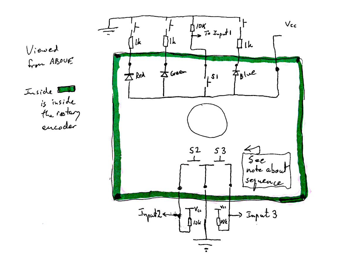
But! I found the datasheet a little hard to read, so here's my "candle"...
Note that I have drawn both the encoder, and some suggested external circuits. Perhaps my arrows should have said "Output 1, -2, -3"... They are outputs from what you see here, intended to go to inputs of, say, an Arduino or Pi.
I was working with 5v. You could use 3v3 just as well, but you might have to adjust the value of the LED resistors.
Note that you can only dispense with the pull ups on S2 and S3, and use the Arduino's lovely setMode(pin,INPUT_PULLUP). On the other hand, S1 is connected to Vcc through the encoder, and thus you use an external pull down resistor, and setMode(pin,INPUT) to monitor that switch.
"Note about sequence": The three pins near the instruction to see this note CERTAINLY connect to switches inside the encoder. I THINK it is the middle pin that is common. They are Normally Open switches, and only close when the shaft is BETWEEN the "click" detent positions. 24 pulses per 360° of rotation. The closures are out of phase, so, (see Wikipedia page. "Incremental rotary encoder" section) you can tell how far the shaft is turned, and in which direction. If the knob on your shaft had an "arrow" on it, you can never, from the encoder alone, tell which way that arrow would be pointing. (I believe one of the other Sparkfun encoders DOES allow you to know.)
Turning to the stuff at the top of the diagram. When I used 5v and a 1k resistor, I had 2mA through the blue LED. 1k for each LED gave roughly uniform brightness.
The switch shown is normally open, and closes momentarily if you press down on the shaft. (Stays closed as long as you keep pressing.)
In the diagram above, two of the three switches shown are called "S2" and "S3". Switches "A" and "B" in what follows correspond to those two switches. (I've had to change the names because I am not yet sure wether "S2" is "A" or "B"... but you can still use what follows! Write and tell me, if you get to the bottom of which is which!)
When the shaft of the encoder is rotated, those switches open and close very rapidly. (I haven't got to the bottom of exactly how many times for 360°... but at least 24.)
The method is in the following madness...
The openings and closings of A happens in between the openings of B. Furthermore, which one "opens first" depends on which way you are turning the shaft.
In the following, look closely at the state of B when A goes from closed to open. (We call that moment "a positive edge". (If the switch goes from open to closed, it is a "negative edge".) Very simple wiring (shown as part of the external circuits at the top of the page) change a closed switch to a high signal from an output, an open switch to a low output.)
As I said... look at B when A goes from low to high. The vertical dotted green line marks the critical moment, for each direction of rotation.
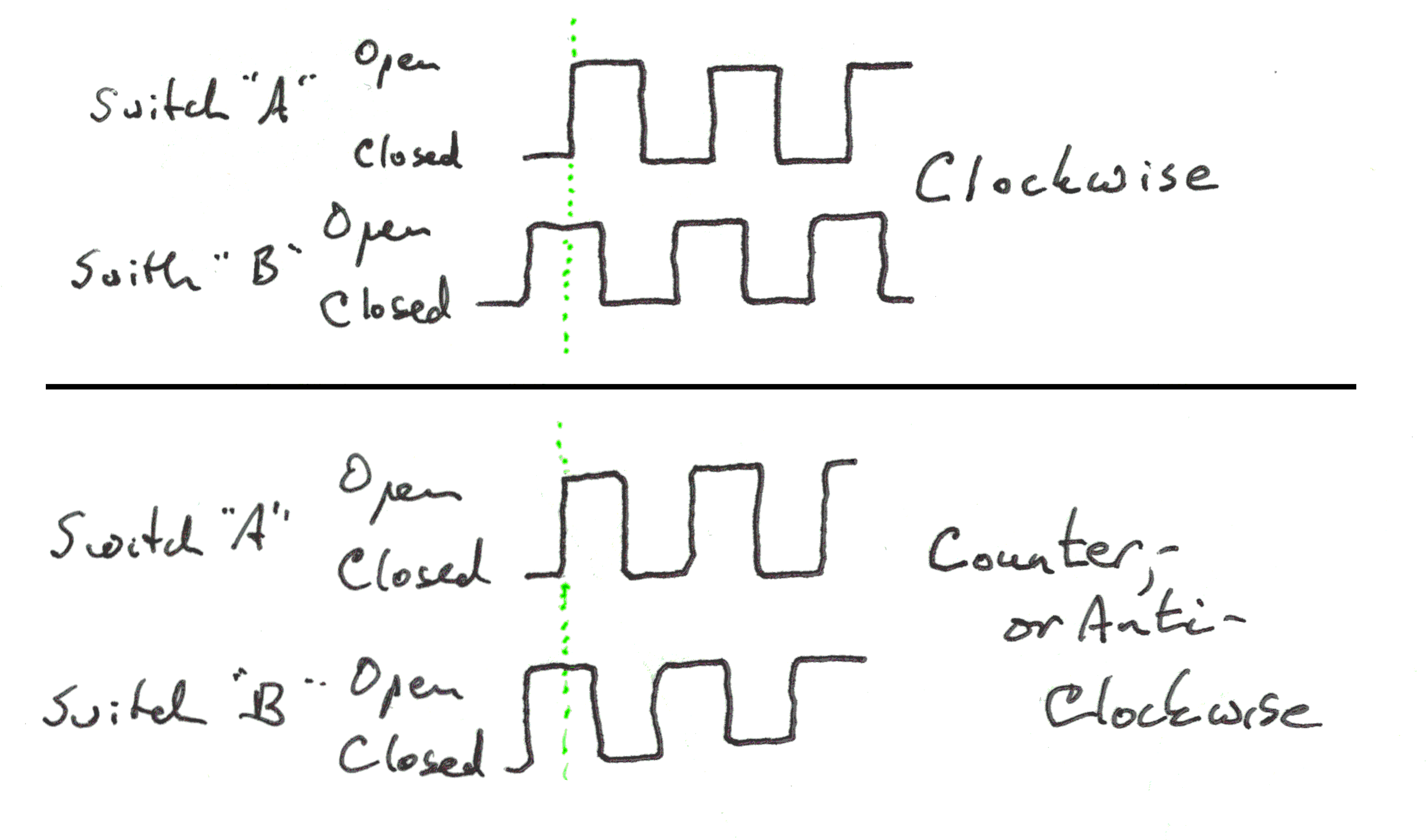
See the beauty of the device? Simply seeing an edge, anywhere, tells you that the shaft is being turned. If B is low when A has a positive edge, the shaft is turning clockwise. If B is high when A has a positive edge, the shaft is turning the other way.
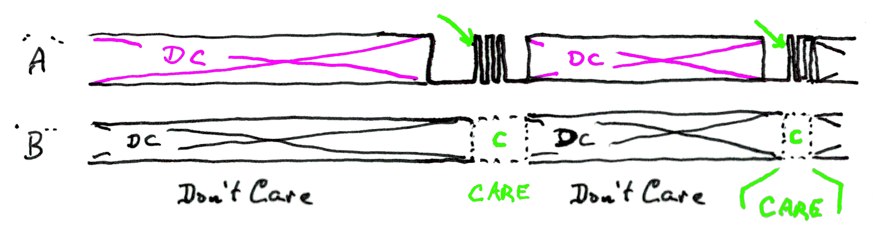
Most of the time, we don't care about the rotary encoder.... apart from...
We DO care about what's happening there, when there is a positive edge (switch going from open to closed) on switch "A". Which is what I've tried to say in the following. The "DC" ("Don't Care") for A is in magenta, because we "care" a little bit. We want to know if there's a positive edge. We don't care about the negative edge after the positive edge that got our attention before we went into the "don't care" state.
Interrupts were made for things like this. They are a bit scary at first... but... You Can Do Them.
That, alas, must be a story for another time. Of course there are other resources! Perhaps the Sparkfun sample code for this device uses interrupts?
The job CAN be done with polling. What I wrote about detecting pulse trains on an Arduino, without interrupts, may help, if you want to go that route.
Here's one last thing for you... a discussion of the problem of "switch bounce"... with a cure!
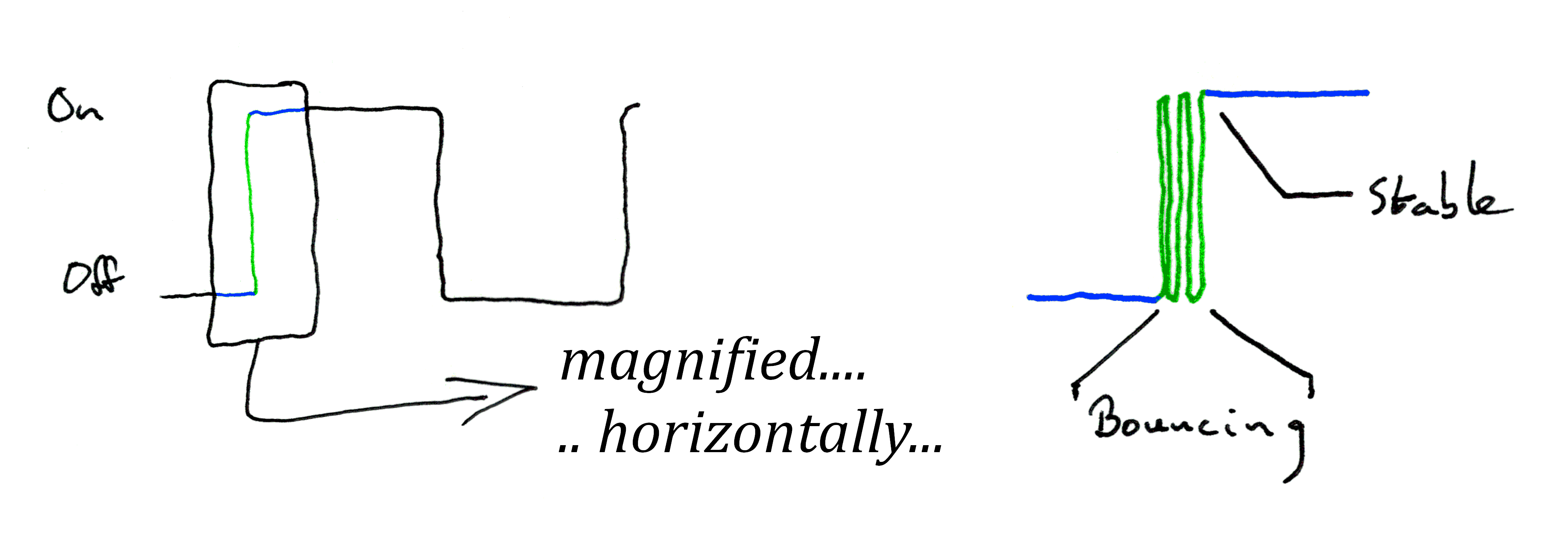
At any human-perceivable time scale, switches just go from "on" to "off" and vice versa.
If, however, you "look" at a mechanical switch "under a microscope", you will discover what the diagram above tries to show...
For a moment, as the switch is closing... and again when it is opening... it jumps back and forth a number of times between "open" and "closed". This is called "switch bounce".
This could be a nuisance for the designer who is unaware of the phenomenon.
Happily, there is a simple solution, in software. If you are, for instance, watching for positive edges, all you need to do is to STOP watching for a very brief moment... 8ms?... after seeing the FIRST positive edge of the short series that will arise due to bounce as the switch is opening.
You must also guard against the detection of false "positive edges" during the bouncing as the switch is opened.
(And all of that, "the other way up" has to be implemented if you are watching for negative edges.)
If it were easy, where would be the fun?
There's a nice bit of Arduino code at the HowToMechanics page about the incremental rotary encoder. The good news is that it doesn't use interrupts. I haven't tried the code, but it looks good, at a cursory glance. Certainly a starting place, if nothing more!
I'm not sure if it will suffer bounce issues... but there are ways around them, if you do. And it relies on fairly rapid repetitions of the loop() routine... but it "should work" for many wants!
And then there's the more sophisticated answer from AllAboutCircuits. They use interrupts, and a hardware "answer" to debounce. (I think I could put the "debounce" into the software... but could be wrong!) (I haven't tried this, either! Let me know how you get on? At least I've saved you working out the pinout!!)
The general idea of these pages is it make it easier for you to use some little gizmo that I found fun. I hope this one achieved that? Your thoughts and anecdotes, welcome. What are you using one of the devices discussed here for? Virtues? Problems? (Especially anything not mentioned above that you think the next person reading this would like to be told.)
If you found this of interest, please mention in forums, give it a Facebook "like", Google "Plus", or whatever. I've almost given up writing these pages, because it seems they are seldom read, and of course not every reader will use them... so... is there any point? If you want more of this stuff, help!?
Click here to visit my main homepage where you
can explore other areas, such as education, programming, investing.
![]() Page tested for compliance with INDUSTRY (not MS-only) standards, using the free, publicly accessible validator at validator.w3.org. Mostly passes. A few "bad attributes" due to Google+ button, etc.
Page tested for compliance with INDUSTRY (not MS-only) standards, using the free, publicly accessible validator at validator.w3.org. Mostly passes. A few "bad attributes" due to Google+ button, etc.
....... P a g e . . . E n d s .....