This page is browser friendly, by the way. Make your browser's window less wide than your whole screen and you will find the narrower columns much easier to read.
On this page you will find Arduino code, the heart of which is parceled into a tidy subroutine, to look at an input, and report whether a fairly stable stream of pulses is arriving. (A stream of on/ off/ on/ off.. transitions).
If you have read (or are considering reading!) other of my tutorials, I should tell you that the one you are reading now is not typical. It covers more ground, but goes into less detail and gives you less help than a typical SheepdogGuides tutorial.
The subroutine explained here can be "plugged into" other programs with very little extra code needing insertion. It can look for the pulse stream on whatever pin suits you. It does not use interrupts, but does rely on you not to divert the processor with any time consuming interrupt processing. The Arduino will not "hang" inside the subroutine if it is called when the input is not changing, or only changing slowly. The subroutine does need you to supply a nice "clean" pulse train... bouncing contacts will cause misreads.
It doesn't matter what point in the pulse train you call the subroutine... it can "read" the pulse train regardless of whether the signal is high or low when you call the subroutine.
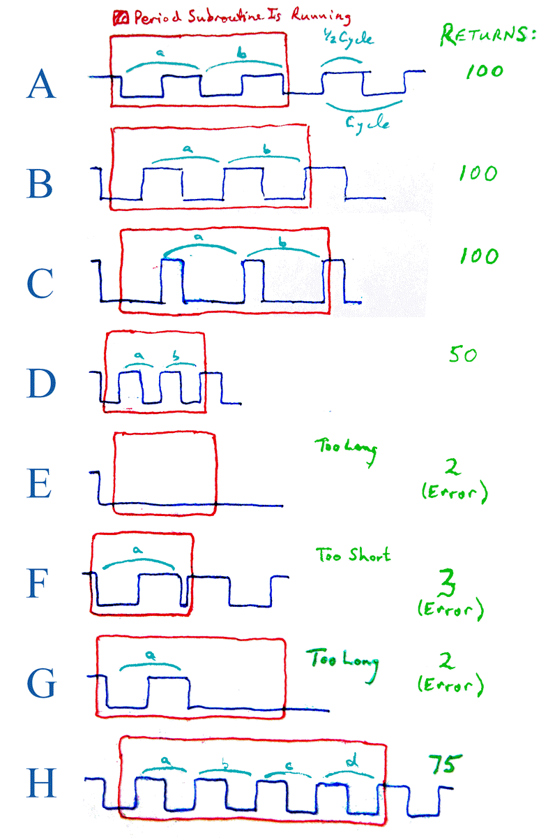
The following will get more extensive explanation another time. For now: It illustrates some of the cases which can arise, with one set of calling parameters used in cases A-G. In "H" the "HowMany" parameter was changed. Don't struggle with the diagram too hard at this point.
I'm not yet sure of the range of frequencies the subroutine can detect. I think the pulse train source I've been using can generate either 800 Hz or 1750 Hz. During my testing, the subroutine has been returning values of about 182 and about 80. (The value returned is a measure of the length of one cycle, hence the large value for the low frequency pulse train.) It is hard to see how a pulse train could be too slow for the subroutine, but I can't tell you what pulse train is too fast for the subroutine... although it will tell you... there's an error code for "the signal is changing too rapidly for me to measure the cycle length." I was using a ModernDevice.com RBBB, a clone compatible built around an ATmega168, and the version 0017 Arduino IDE. Hmmm... does "ATmega168" tell you the critical datum, the basic clock speed? (The RBBB is sold today with an ATmega328, by the way.)
A call of the subroutine looks like this...
wAnswer=DCDWpt(20,8,200,0);
It returns a word (unsigned 16 bit number). The bigger the word, the slower the pulse train detected. The subroutine will return error codes (0,1,2,3,4,5 or 6) if while it was executing, the conclusion was reached that no pulse train was apparent.
(By the way... The name, "DCDWpt" arises from "Dirt Cheap Dumb Wireless", a project to create some little modules to transmit data to a central monitor using inexpensive RF modules. An Arduino would need about $30 in extra hardware to monitor the temperature in two places, plus the light level at one and an open or closed switch at the other. These two "places" could be several hundred feet from the Arduino, and no wires needed. The DirtCheapDumbWireless initiative is still in its early days... products are not on sale to the public yet... but they are working!
In order to detect a pulse train, the subroutine goes through the following....
A) It checks the state of the input immediately upon beginning execution... and then waits for that state to change. This is to "throw away" whatever remains of the half cycle currently occurring. If while waiting for the first state change, the subroutine has to wait "too long" (explained in a moment), the subroutine will assume the signal is "stuck" high or low (or that the frequency of the pulse train is too low to interest us), and return 1.
B) The subroutine then enters a loop, in which it will attempt to measure the length of a number of full cycles of the pulse train. Each half cycle will be timed, and if any one of them is too short, the subroutine aborts, and returns an error code (3 or 4, for "too short" in first or second half-cycle of a pair, respectively).
Each full cycle is also timed. If a full cycle is not completed quickly enough, the subroutine aborts, and returns an error code (5 or 6, for "too long" in first or second half-cycle of a pair, respectively).
C) If the subroutine has not been aborted due to an error condition, as explained above, after the last cycle has been timed, the time that cycle took is returned as the result from the subroutine.
That's "the big picture". Bear with me... next I'll tell you a bit more about using the subroutine, then we will start again, and take you through your first use of it.
Remember the example of a call of the subroutine? I'll repeat that here...
wAnswer=DCDWpt(20,8,200,0);
Here's what you can specify when you call DCDWpt...
The "20" defines what is a "TooShort" half cycle. If you are measuring high frequency pulse trains, you will have to set this low... but the higher you can set it, the more often the subroutine will reject noise on the input.
The "8" says how many "good" cycles must be seen for the subroutine to report that a "real" pulse train is being seen on the input.
The "200" says how long the subroutine should wait for a cycle to finish. Set this as low as you can, but with a little margin. The higher you set it, the longer the subroutine will take to finish executing. But the lower you set it, the lower the maximum detectable frequency falls.
The "0" is a parameter which I suspect may be of little use. It introduces some wait cycles inside all of the critical loops within DCDWpt. It might be useful for slowing execution down in some debugging circumstances. It would also allow the subroutine to measure even slower pulse trains that the slowest that you can detect with the "WaitFor" parameter set to 65535. When I know how slow that is, I'll know if there's any need for the 4th parameter. I suspect not!
Right! By the magic of wordprocessing, the above was written after what follows. I've written that out in various forms several times now, and at last it is, I hope, almost coherent?
What follows is not well edited yet, but, if you are diligent and patient, I think you can extract from it the subroutine promised above.
I will take you through steps which should help you bypass some of the debugging headaches which you might otherwise encounter.
There are frequent references below to DCDW transmitters and receiving modules. All you need to know in order to make use of what follows is that the receiver sends a signal to the Arduino. That signal is either a stream of random "on"s and "off"s... and that could mean that the signal was "stuck" high or low for protracted periods, or changing rapidly.... OR, when a DCDW transmitter is sending, the signal from the DCDW receiver to the Arduino will be a pulse train of a fairly stable frequency.
Set up an Arduino with an LED and resistor to ground from D13.
Put the following program into the Arduino, just to check the LED....
//DCDW Start DCDW
//LED and resistor on pin 13...

const int LEDpin=13;

void setup()
{
pinMode(LEDpin,OUTPUT);
};

void loop()
{
LEDOnOff(0);
delay(600);
LEDOnOff(1);
delay(50);
}

void LEDOnOff(byte OnOff)
//Pass zero to turn off, anything else to turn on.
//As presented here, works with an LED connected to
//a resistor to ground. If you prefer to connect
//through the resistor to 5v, then just change
//the "==0" to "!=0", and LEDOnOff will work as
//before, i.e. calling LEDOnOff(0) turns it off.
{
if (OnOff==0)
       {digitalWrite(LEDpin,LOW);}//no ; here
  else {digitalWrite(LEDpin,HIGH);}
}
All the above does is establish an easy-to-call routine, LEDOnOff(zero or one), to turn LED off or on. In the test program above, the LED should... you see this, don't you?... go on briefly, then off for a longer period, over and over. Be sure you're seeing on/ OOOFFFFFFF/ on/ OOOFFFFFF..., not the opposite. It is easy to have any one of several things backwards.
We don't need the routine or the LED to use DCDWpt, but it will help us in debugging new installations to have it.
Okay... now connect a source of a pulse train, e.g. some DCDW equipment, with a way to generate pulse train of a fixed frequency when you press a button. Connect the source of the pulse train (e.g. the output from a DCDW receiver) to D4 of your Arduino. You can, of course, change that... by changing just the "const DCDWinput = 4;" line below... but I'm using I/O D4 for the rest of this essay.
Enter the following....
//DCDWGetStarted1
//ver 25 Feb 11
//started 25 Feb 11

//A program for users just getting started
//   with DCDW modules

const int LEDpin=13;//I/O line with LED.
//   LED should go through resistor to ground.
//   Set pin high to turn LED on.
//   Many Arduinos already have an
//   LED and resistor connected thus for you.

const byte DCDWin=4;//I/O line used for input to Arduino
//   from DCDW receiver. Change just this line of
//   program if which I/O line changed. Both the
//   driving program and the fundamental DCDWpt
//   subroutine access this global constant.


void setup()
{
pinMode(LEDpin,OUTPUT);

//From here to "END DCDWpt prep"... code to be inserted
//in programs using the DCDWpt1 subroutine. Things MAY
//be modified, e.g. which pin the DCDW module feeds.
//
//The program using the subroutine also needs the line
//above which defines the global constant DCDWin, but that's
//the only "messy bits".

pinMode(DCDWin,INPUT);

//digitalWrite(DCDWin,HIGH);//Connect the internal
    //pull up resistor, if your DCDW receiver does
    //not have something to source or sink, regardless
    //of output state. (Mine did... i.e. I did
    //NOT want this line in my program.)

//END DCDWpt1 prep
};

void loop()
{
if (digitalRead(DCDWin)==HIGH)
       {LEDOnOff(1);}//no ; here
  else {LEDOnOff(0);}
delay(20);
}

void LEDOnOff(byte OnOff)
//Pass zero to turn off, anything else to turn on.
//As presented here, works with an LED connected to
//a resistor to ground. If you prefer to connect
//through the resistor to 5v, then just change
//the "==0" to "!=0", and LEDOnOff will work as
//before, i.e. calling LEDOnOff(0) turns it off.
{
if (OnOff==0)
       {digitalWrite(LEDpin,LOW);}//no ; here
  else {digitalWrite(LEDpin,HIGH);}
}
That little program, again, doesn't take us very far, but many of us don't have oscilloscopes to "see" what is coming from the DCDW. The program above can be used for a number of tests....
It rapidly samples the input to the Arduino from the DCDW receiver. When the DCDW transmitter is not transmitting, you will probably get a random sequence of randomly long "on"s and offs. If you find that the input is ALWAYS high, or ALWAYS low, suspect a problem. Try disconnecting the wire from the DCDW receiver to the Arduino, and hard wiring the Arduino's input high first, and then low. The LED should report "high" (be on) then "low". If it doesn't, get that much sorted out, because none of the following is going to work until you do!
With the program above running, and the DCDW receiver's output feeding the Arduino, and the DCDW transmitter sending something to the DCDW receiver, you may not notice much difference in the behavior of the LED. The sample rate of the program is "glacially slow", relative to the pulse train that DCDWin should be seeing. Whether the program samples the input at a "high" moment or a "low" moment will be virtually random... But!... you should at least see the input low sometimes, high other times.
And you will have debugged various things which could get in the way of subsequent programs giving you meaningful output.
My DCDW transmitter IS working!
When I press either of the "send pulse train" buttons, if I have the antenna close to one of my old CRT monitors, I get interference on the screen!
Ah, the sophisticated test tools of the amateur electronics "engineer"!
Okay... now we have to jump in at the deep end somewhat.
Now load your Arduino with the code which appears at the end of the page. It is merely a development of what we've done already, but loading it wholesale is your best bet.
I've put in some odds and ends to make using the Arduino development system's basic serial monitor possible. That isn't "necessary" for DCDW work... but it is necessary for this program which exercises DCDWpt, because messages from the program about what it is "seeing" are passed to the serial monitor. (If you aren't familiar with the basic serial monitor... build into the basic Arduino development environment... see my introduction to the serial monitor.)
Those odds and ends include...
In setup():
Serial.begin(9600);//For access to serial monitor channel
... and...
//debug
delay(100);
Serial.println("Starting...");
delay(200);
//end debug
.. which just puts your mind at rest, if you do a reset, and want to be sure that the reset happened.
In loop(), the following is new, replacing the old things we had there....
Serial.println(DCDWpt(50,5,250,0));

if (digitalRead(DCDWin)==HIGH)
       {LEDOnOff(1);}//no ; here
  else {LEDOnOff(0);}
delay(100);
All we REALLY need is the Serial.println line, but the other stuff... periodic sampling of DCDWin, and a slight delay each time through the loop are helpful and at worst harmless.
DCDWpt returns a number. If it is a low number, it is an error message... more on this later. A higher number indicates that a regular pulse train, with a frequency between certain bounds, was detected. The bigger the number, the longer the duration of the last cycle of the one or more cycles sampled. We'll go into the parameters of the subroutine call another time. The sub-routine "throws away" whatever remains of the half cycle occurring at the moment the subroutine is called, and then measures the duration of one or more cycles (set by parameter), aborting with an error message if a half cycle is too short (definition set by parameter) or a cycle too long (definition set by parameter).
TooShort: 8 bit unsigned
HowMany:  8 bit unsigned
WaitFor: 16 bit unsigned
Knobble: 16 bit unsigned
TooShort: Set to a little less than HALF of your expected shortest pulse train result.
HowMany: The higher you set it, the more "robust" your readings will be... but calls will also take longer. Making it higher does not make the readings more accurate. For that: Read, say, five times. Throw away the highest and lowest readings, average the others. Set to about 8 in many cases.
WaitFor: Set to a bit more than your largest expected valid result.
Knobble: Set to zero when not debugging. Probably of little use, even then!
0: TooShort is too small. Must be >= MinNotErr
1: Initial state (of input to Arduino from DCDWreceiver) persisted for longer than "WaitFor", i.e., the scrap of half cycle the program was trying to "throw away", before starting to time complete half cycles, was too long.
2: First 1/2 cycle of a pair was longer than "WaitFor". This can also be assigned to report what is given for error code 5 below without giving up too much information.
3: First 1/2 cycle of a pair was shorter than TooShort. This can also be assigned to report what is given for error code 6 below without giving up too much information.
4: Cycle... the two half cycles in one pair... was too short to distinguish from an error code. There did appear to be a sensible pulse train, but the frequency was so high that the "right" response would have looked like the subroutine was returning an error code.
5: Second 1/2 cycle in a pair didn't finish before whole cycle was longer than WaitFor. See also note at Error Code 2.
6: Second 1/2 cycle in a pair was shorter than TooShort. See also note at Error Code 3.
When there is no transmitting DCDW module active in the "hearing" of the DCDW receiver, you would expect the subroutine to return one of the errors 1-6 inclusive.
If the signal from the transmitter dies while the subroutine is reading the device, a mis-read can occur.... perhaps not a SERIOUS flaw??? As long as calling software "filters" readings, discarding "jitter"? I need to discuss this further with you at some point, but it isn't going to happen today.
As long as the typical duration of a pulse train is quite long compared to the time it takes for DCDWpt to inspect it (which is likely to be the case), then the "problem" above will not arise often.
When it does one of two things will happen: Either the reading taken will return a number which is lower than the true length of the cycles in the pulse train, up to the last one, OR DCDWpt will return either error code 3 or 6.
I've called this program DCDWptrain. It incorporates a call to DCDWpt, the subroutine this whole page has been about.
Before going far, have a look at the loop() routine....
void loop()
{
//1
DCDWresult=DCDWpt(20,8,200,0);

//2
Serial.println(DCDWresult);

//3
if (digitalRead(DCDWin)==HIGH)
       {LEDOnOff(1);}//no ; here
  else {LEDOnOff(0);}

//4
if ((DCDWresult>60)&&(DCDWresult<100)) {BeepBeep(0);};
if ((DCDWresult>170)&&(DCDWresult<190)) {BeepBeep(1);};

//5
delay(100);
}
At "//1", we make a simple, normal call of DCDWpt, with parameters suitable to the source of pulse trains I was working with, a DCDW two button/ fixed frequencies "key fob".
At "//2", we send the result of DCDWpt to the serial monitor, so the user can see what DCDWpt "said".
At "//3", we turn an LED on or off, depending on the instantaneous state at that moment of the signal which may be carrying a pulse train. This is a pretty "rough and ready" debugging aid... but if that LED is always on, or always off, suspect something amiss!
At "//4", is a little silliness... don't waste time trying to understand it all if the following doesn't make sense easily. The little silliness just added an extra indication that my DCDW equipment was working. Peering at the stream of numbers arising on the serial monitor from across the room proved tedious and wasn't any fun, anyway.
"BeepBeep(0)", with the piezo buzzer I put on my Arduino's pin 12.. hardcoded! for shame!... makes a noise. "BeepBeep(1)" makes a slightly different noise.
With the DCDW hardware I had connected, providing the pulse train, the system returned about 80 when one of the buttons on the DCDW transmitter was pressed, about 182 when the other button was pressed.
The "delay(100)" at "//5" is just to slow everything down, so that the above happens less than ten times a second.
You've been good... unless you skipped to "the last page".... Here's the code...
//DCDWptrain1
//ver 25 Feb 11, 2:00
//started 25 Feb 11, 12:46

//A demonstration program for DCDWpt1, a generalize
//"Read the DCDW signal" subroutine which does not
//use interrupts.

const int LEDpin=13;//I/O line with optional LED.
//   Change if you wish. Many Arduinos have an
//   LED and resistor on I/O D13 on the PCB.
//   LED should go through resistor to ground.
//   Set pin high to turn LED on.

const byte DCDWin=4;//I/O line used for input to Arduino
//   from DCDW receiver. Change just this line of
//   program if which I/O line changed. Both the
//   driving program and the fundamental DCDWpt
//   subroutine access this global constant.

word DCDWresult;

void setup()
{
Serial.begin(9600);//For access to serial monitor channel
pinMode(LEDpin,OUTPUT);//For non-esssential LED

//Here begins unnecessary bit... connected with beeper on
//D12....

pinMode(12,OUTPUT);//For non-esssential beeper... pull low to turn on
digitalWrite(12,HIGH);

//From here to "END DCDWpt prep"... code to be inserted
//in programs using the DCDWpt1 subroutine. Things CAN
//be modified, e.g. which pin the DCDW module feeds.
//
//The program using the subroutine also needs the line
//above defining the global constant DCDWin, but those
//are the only "messy bits".

pinMode(DCDWin,INPUT);
//digitalWrite(DCDWin,HIGH);//Connect the internal
    //pull up resistor... not always necessary,
    //sometimes a Bad Idea... depends on how your
    //DCDW receiver was built.

//END DCDWpt1 prep


//debug
delay(100);
Serial.println("Starting...");
delay(200);
//end debug

};//end of setup()

void loop()
{
DCDWresult=DCDWpt(20,8,200,0);

Serial.println(DCDWresult);

if (digitalRead(DCDWin)==HIGH)
       {LEDOnOff(1);}//no ; here
  else {LEDOnOff(0);}

//Extra "unnecessry" bit to "show off" device....
if ((DCDWresult>60)&&(DCDWresult<100)) {BeepBeep(0);};
if ((DCDWresult>170)&&(DCDWresult<190)) {BeepBeep(1);};


delay(100);
}

void LEDOnOff(byte OnOff)
//Pass zero to turn off, anything else to turn on.
//As presented here, works with an LED connected to
//a resistor to ground. If you prefer to connect
//through the resistor to 5v, then just change
//the "==0" to "!=0", and LEDOnOff will work as
//before, i.e. calling LEDOnOff(0) turns it off.
{
if (OnOff==0)
       {digitalWrite(LEDpin,LOW);}//no ; here
  else {digitalWrite(LEDpin,HIGH);}
}

void BeepBeep (byte Which)
//"Unnecessary", except as part of "ShowOff" frill...
{
byte reps=6;
byte d1=30;
byte d2=80;

if (Which==0) {d1=100;d2=10;reps=2;};
do{
digitalWrite(12,LOW);
delay(d1);
digitalWrite(12,HIGH);
delay(d2);
--reps;
} while (reps>0);
}

//Below here... all for DCDWpt subroutine and things
//used only by that.

word DCDWpt(byte TooShort, //byte: unsigned, 8-bit
            byte HowMany,
            word WaitFor, //word: unsigned, 16-bit
            word Knobble)
{
word Ticks;
word Ticks2;
byte bErr;
boolean boStateWasHigh;
const byte MinNotErr=7;//Set this to 7 if max used error code is 6, etc

//Init certain variables, check certain potential errors...
bErr=255;//Says "no error seen yet"
boStateWasHigh=boStateHighNow();
if (TooShort<MinNotErr) {bErr=0;};

//Now start into main portion of the code of the SR...
if (bErr==255)//level 1
{
//Wait for partial 1/2 cycle to finish. Note that the
//partial 1/2 cycle can be nearly as long as WaitFor...
//Unlikely if a normal pulse train present, and its
//duty cycle is near 50%... but this special case causes
//no problems, if it arises.

Ticks=0;
Ticks2=0;//Not used... but to keep loop time constant
do { //level 1 do... while
  sid(Knobble);
  ++Ticks;//Equivalent to Ticks=Ticks+1
  ++Ticks2;
  if (Ticks>WaitFor) {bErr=1;};
  //Serial.print(word(bErr));
  //Serial.println(bErr);
} while ((bErr==255) && (boStateWasHigh==boStateHighNow()));
// && is boolean "AND" operator
//Partial 1/2 cycle has finished... or taken too long,
//as specified by WaitFor, to finish, which is an error.
  }//ends the "level 1" if clause

boStateWasHigh=(!boStateWasHigh);//Prepare to watch for next edge

if (bErr==255)//"if" level 2
{
//Proceed into heart of SR... the timing of multiple (HowMany) pairs of
//1/2 cycles, watching all the while for a TooShort 1/2 cycle, or a full
//cycle not completed before WaitFor
//SR returns the length of the last cycle timed.
do { //"do" level 1
//here begins "body of do/while, level 1"
Ticks=0;
Ticks2=0;//Not used here... but keeps loops running at same speed
do { //"do" level 2a
++Ticks;
++Ticks2;
if (Ticks>WaitFor) {bErr=2;};
sid(Knobble);
} while ((boStateWasHigh==boStateHighNow())&&(bErr==255)); //end "do" level 2a
boStateWasHigh=(!boStateWasHigh);//prepare to read next 1/2 cycle
if (Ticks<TooShort) {bErr=3;};//First 1/2 cycle of pair was too short

{
//do NOT reset Ticks to zero here
Ticks2=0;
do {//"do" level 2b
++Ticks;
++Ticks2;
if (Ticks>WaitFor) {bErr=5;};
sid(Knobble);
} while ((boStateWasHigh==boStateHighNow())&&(bErr==255));//end "do" level 2b
boStateWasHigh=(!boStateWasHigh);//prepare to read next 1/2 cycle.
if (Ticks2<TooShort) {bErr=6;};
}//end "if" level 3. Ticks now hold time CYCLE took, Ticks2= time of 2nd 1/2 cycle

//here ends "body of do/while, level 1"

--HowMany;
} while ((HowMany>0)&&(bErr==255));//end of "do" level 1
}//end "if" level 2. No Else clause.

//And finally, outside all loops and "ifs" above...
if (bErr==255) {return Ticks;}//no ;here
  else {return bErr;};
}
//End of main SR, DCDWpt1, only one called directly by "higher"
//levels of program.

boolean boStateHighNow()
{
  if (digitalRead(DCDWin)==HIGH)
       {return true;}//no ; here
  else {return false;}
}

void sid(word c1)
//"Slow It Down"... a routine to make the main subroutine
//run more slowly. How much more slowly determined by
//value passed to DCDWpt in Knobble.
//Pass zero for minimum "slow down"
{
if (c1>0) {
   do {
       delay(1);
       --c1;
      } while (c1>0);
}//end of if...
}//end of SR sid
I hope that code proves useful to you. I'd be interested to hear what you do with it, what "fixes" you think it would benefit from, what success you have with it. If you can test the envelope for me, I'd be interested to know what frequencies it can be used on. I'll need details of your Arduino, or clone, too, of course... I'd prefer data from Arduinos and clones without anything "extra" going on, in particular in respect of extra interrupt handlers.
![]() Page tested for compliance with INDUSTRY (not MS-only) standards, using the free, publicly accessible validator at validator.w3.org
Page tested for compliance with INDUSTRY (not MS-only) standards, using the free, publicly accessible validator at validator.w3.org
CSS behind the page checked, at least once upon a time!, with http://jigsaw.w3.org/css-validator/
Why does this page cause a script to run? Because of the Google panels, and the code for the search button. Also, I have some of my pages' traffic monitored for me by eXTReMe tracker. They offer a free tracker. If you want to try one, check out their site. Why do I mention the script? Be sure you know all you need to about spyware.
....... P a g e . . . E n d s .....