This has good information, and a search button at the bottom of the page
I am old fashioned. I disavow any responsibility for things you may elect to do. In particular, I disavow any responsibility for any consequences arising from connections you make between devices. You can't just plug "anything" into your computer or anything else!. In particular, make sure that you aren't assuming that an RS-232 interface can be connected directly to, say, an Arduino or BASICstamp, or PIC or other microprocessor. There are notes on some of those issues on my serial ports page, for those of you who need them.
Enough "lawyer feeding".... let's turn to the Fun Stuff....
If you have already read my page "dt4r" (the illustrations just a little way down the page will be familiar), you can jump ahead to material HERE that isn't duplicated THERE!
This is one of the more advanced tutorials in a series which shows you how to link two devices using serial comms. In the tutorials, the "devices" are a Windows PC running programs written with Delphi and an Arduino... neat little, inexpensive, fun, capable microprocessor. However: Either device could be replaced by another... many of the issues discussed here are general, but I find that principles are best understood when backed up by examples of their application.
Click here if you want to know more about the source and format of these pages. It may be easier to read this if you re-size the window, so that it does not use the full width of your screen.
The Delphi sourcecode is available for download. The Arduino sourcecode is presented here in full, and you can copy it and paste it into your Arduino development environment for compilation and upload to your Arduino.
This page are a bit rough and ready. Explanations are sketchy. But the code DOES work. I'll try to come back to this and improve it later.
Before I present the tutorial: A challenge for you: If you are an advocate of another language, write whatever is needed to connect a PC (or other device) to the Arduino with switch and LED and Arduino program as presented here. In other words, replace what is plugged into the Arduino, but leave the Arduino side of things as it is in the essay below.
If you succeed, and publish the details, with full sourcecode for the language of your choice, I would be glad to post a link to your work here, just send me the URL.
Right... onward...
For many years, for a number of different reasons, I've wanted to hook a microprocessor to a "big" computer, and have them talk to one another. These days (August 2010) I am using the wonderful Arduino for microprocessor projects, and a Windows XP computer for my "main" work. The material below could be used with other devices. In particular, if your objective is to connect some serial device to a "big" PC, you will find helpful material, I hope.
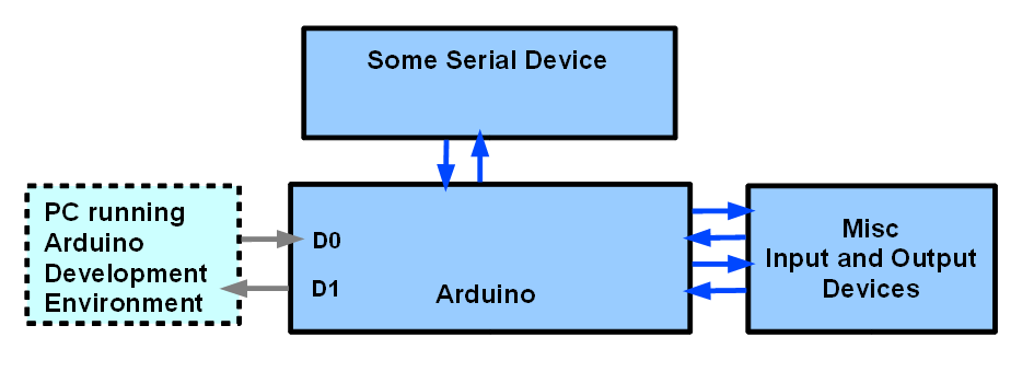
In the diagram below, if you assume that the "some serial device" is a PC, you see two PCs attached to the Arduino. The one on the left is there for when you are setting up the Arduino to do whatever you want it to do with the other PC. It would normally unplugged, taken away after the system had been built.
The set up above is pretty general. Even without restricting what it implies, you can have two scenarios.
In order to explain the scenarios, I need to say what I mean by "Master" and "Slave" in the rest of this essay. A "master" device is in charge. The "slave" device will "speak when spoken to". It may get on with various things when it isn't commanded by the master to be doing other things, but it will not "come up" on the serial channel, aka "serial link" between master and slave unless the master has told it to. The master may "speak" to the slave in an imperious manner, just issuing a command, and assuming the slave will execute it without any reply. If, for instance, there was an LED attached to the slave, the master might send a "turn LED on" command". Or, the master might "say" "Turn on the LED, and tell me that you've done it." In the latter case, the master would have to be programmed to look for the slave's reply.
You can build systems like the above in which the "Some Serial Device" is the master, and the Arduino is the slave, and you can build systems the other way around (Arduino as master, other serial device as slave.) In the work so far within this tutorial, an example of a Windows XP computer as master, with an Arduino as slave has been created. (The hard parts of doing the reverse are all solved, and part of the first solution.)
It is all well and good thinking in general terms, but eventually it is necessary to get down to cases. For the work to be discussed, this is the set-up I was using....
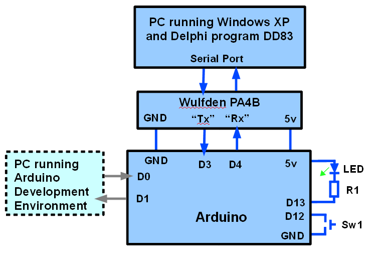
The Wulfden module is a neat, inexpensive solution to the problems arising from the fact that the PC uses RS-232 serial comms and the Arduino is a TLL device. I'll try to expand on that later. (See my serial port page, for a badly written "answer", in the meantime.("Hardware" section, near top.)) N.B.: The "Rx"/"Tx" markings on the device, and on the diagram above cause people no end of confusion. They stand for "transmit" and "receive"... but relative to which device??? There's a signal FROM the PC TO the Arduino that is marked "Tx" above.. and we are transmitting from the PC to the Arduino.... but the Arduino might well call that line "Rx", as it is the line the Arduino is receiving on. Not rocket science, but easy to get turned around. Follow the diagram: Connect the signal marked "Tx" on the PA4B to digital pin "3" of the Arduino, the signal marked "Rx" on the PA4B to digital pin "4" of the Arduino, enter the Arduino programs given below, and all will be well.
I suppose this is the place to say something about the connection from the PC running the Arduino Development Environment to the Arduino. It goes to digital pins 0 and 1. I'm not doing anything "clever" here... that's just the normal connection, over which you send programs ("sketches") to the Arduino from the PC where they are compiled.
Apologies for that little diversion. The problems this tutorial sets about solving are rife with "little details", all of which have to be Got Right.
Some day I will re-write all of this, and give you tutorials of my usual style... nice, progressive, help you understand what's happening bit by bit tutorials.
At the moment, the best I can offer you, by way of a "gentle" path to the material which is farther down the page you are reading now is an early draft of tutorials about DD81 and DD82. That page starts with much of what you've already seen, if you read to here from the top of the page. But at the point on that page corresponding to this point, things change.
I don't have time to write it like that now. The work of developing the code is well along. The code needs rough edges "sanded", but it WORKS. So for now, I will tell you about the "final" (for now!) "masterpiece". I'm doing that in the page you are reading. The stages I followed to reach the "final" (for now!) stage are explained in the page I gave you a link to a moment ago.
You can download the free sourcecode for DD83. The zip file also includes a compiled copy of the application. The compiled version is hard coded to operate on COM1 at 9600, with no handshake.
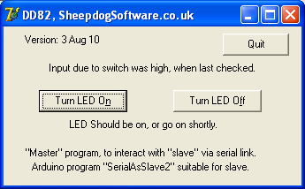
If you run that, you should see................................
If it is connected to an Arduino, and the Arduino is running the right software (we'll come to that), and the Arduino has the LED and switch shown above, then....
If a user clicks on the "Turn LED On" or "Turn LED Off" buttons, on screen, on the "big" PC, and the LED on the Arduino will go on or off. If a user presses the switch connected to the Arduino, and the text near the top of the DD83 window will change, to reflect the state of the switch. (When both DD83 and the program in the Arduino are running, the "... when last checked" qualification becomes academic... the switch is checked by the Arduino, and what the Arduino found is checked by DD83 many times per second.)
Clear? Exciting? It should be! With the ideas in the software here, many, many things become possible. The "switch" could be a temperature sensor. The "LED" could be the heating for a home. And the "LED" (heating) could be turned on automatically whenever the temperature detected was too low. Pretty expensive "thermostat", but just an illustration.
There are a lot of rems in that Delphi code to help you understand what is going on. You don't, by the way, have to do this with Delphi or with a Windows computer as the master. If you know how to connect something else to a serial stream, and can send things to the Arduino over a "Tx to other device" line, and read bytes received over a "Rx from other device" line, you can use the Arduino code I've presented here with the software and serial device of your choosing. I challenge my Arduino friends to do the fairly simple exercise of writing Arduino code to have another Arduino in place of the Windows XP computer in the diagram above. That "master Arduino" would only need a switch and an LED to be "powerful" enough to take the place of the Windows XP machine. The switch would take the place of the "Turn LED On" / "Turn LED Off" buttons, and the LED would take the place of the "Input due to (other!) switch was high/ low..." text. (If you can work up such a device without repeatedly getting confused as to which LED is controlled, and which is reporting, etc, ,my hat is off to you. Would the whole thing be "symmetrical", apart from one Arduino being master, the other slave? I think I'll leave worrying about that for another day when my brain is fresher!) I think it would LOOK symmetrical... but wouldn't actually be symmetrical "inside". Either switch would control the LED on the OTHER Arduino....?
But! Back to today's problem: "All" you need now is the code to be run in the Arduino. That is as follows.
A little detail: The screenshot for DD83 (above) says that "SerialAsSlave2" should be running in the Arduino. That should read "Arduino program "SerialArdAsSlave2" suitable for slave."
One more detail... the rems in the following and much else have not been "polished". There may well be duplications, scraps which moved forward from program to program as the solution was developed. Sorry. I'll work on them, but I can't do that soon.
//SerialArdAsSlave2- Arduino as slave to host connected over serial line
//Complements Delphi program DD83

//version: 03 Aug 2010, tweaked after moved to html

/*MOSTLY working, some rough edges.

Worst(?) rough edge: If the program in the connected serial device
is running, e.g. DD83 is running in a Windows PC, then some
gibberish seems to be sent to the connected device if the Arduino
is reprogrammed while that other program runs.

This is harder to see in DD83 than it was in DD82.

This is the fourth step along a road to having an external
serial device talking with an Arduino. Get the material in
earlier programs working first, then proceed with this
program.

We have Arduino waiting for command from Master, then responding.

I worked with one PC running the Arduino Development
Environment, providing me with the means of programming
the Arduino, and of watching for the output of lines
like Serial.print"a", which passed to the Arduino through
the "programming" cable, the one on the Arduino lines
0 and 1, input to the Arduino, output from it, respectively.

I had the second PC connected to the Arduino via the
second PC's serial port, through a Wulfden PA4B TTL/RS-232
adapter, and what is labeled "Rx" on the PA4B was connected
to D3 of the Arduino, which was being used for OUTPUT. (The
"Rx" on the PA4B is relative to the big PC (or other serial
device "upstream" from the PA4B. The Arduino TRANSMITS (Tx)
while the other device RECEIVES "Rx"

Ever since the first step in developing what we have, the "Tx"
from the PA4B has been connected to D2 in the Arduino. The
Arduino RECEIVEs data via D2, from the PA4B's "Tx" line, fed
from the other serial device.

N.B.: The serial monitor shows BOTH what the Arduino is
SENDING and what the Arduino is RECEIVING. Messy, but works!
To use this, de-rem the Serial.print lines, and change
the speed at which the main loop in the master program is
executing.

You may have to "de-rem" some Serial.print lines in the Arduino code
to see the material promised for the Serial Monitor data stream.

At least SOME buffering is happening somewhere. Remember: I
believe I set the big PCs port up with no handshaking... in
any case, I don't know of any wires in my circuit to implement
it. Even so... if I increase the delay (below) to 1000, and
press XYZ very quickly on the big PC's keyboard, over the next
three seconds, the serial monitor displays aXaYaZ. Hurrah!
I think that NewSoftSerial buffered those data as they arrived,
holding them for when they were asked for.

You could make the bit inside...
if (mySerialPort.available()>0){}
... more clever, with a loop to process all that is incoming
before returning to the rest of "loop()", if you wanted to.
I didn't!

*/

#include <NewSoftSerial.h>
//Yes, NEWSoftSerial... I don't think SoftwareSerial has the
//critical "available()" function, does it?

#define LEDpin 13//no; here. Pin connected to 5v via
//    LED AND current limiting resistor.
#define SwMom 12//no; here. Pin connected to ground
//    via a momentary switch to ground.

#define SerInToArdu 2//no ; here expand rem
#define SerOutFrmArdu 3//no ; expand rem

NewSoftSerial mySerialPort(SerInToArdu,SerOutFrmArdu);//expand rem
byte bToSend=0;
byte bCmndRecd=255;//255 rogue for nothing received

void setup(){

pinMode(LEDpin,OUTPUT);

pinMode(SwMom,INPUT);
digitalWrite(SwMom,HIGH);//"Switch on" internal pull up

pinMode(SerInToArdu,INPUT);//Not actually needed... put in
   //to reassure users as to data direction over
   //serial lines
pinMode(SerOutFrmArdu,OUTPUT);

mySerialPort.begin(9600);

Serial.begin(9600);
};//end "setup()"

void loop(){
if (digitalRead(SwMom)==HIGH){
    //Serial.print("h");
    mySerialPort.print("h");}
  else{
    //Serial.print("w");
    mySerialPort.print("w");};

delay(10);

if (mySerialPort.available()>0){
   bCmndRecd=mySerialPort.read();
   delay(10);
   //Serial.print(bCmndRecd,BYTE);
   delay(10);
   if (bCmndRecd=='n')LEDOn();
   if (bCmndRecd=='f')LEDOff();

   ;
bCmndRecd=255;//Not "essential"... yet. Here.

};
};//end of "loop()"

void LEDOn(){
digitalWrite(LEDpin,LOW);//yes... LOW for ON
};

void LEDOff(){
digitalWrite(LEDpin,HIGH);//yes... HIGH for OFF
};
It could be adapted quite easily to make things work the other way around: With the PC as Slave, Arduino as Master. The "hard parts" of that are done, and in DD83. I look forward to doing that project.... :-)
Many, many of the underlying concepts upon which this system is built... especially the part in the Windows PC... were discussed, explained, etc, earlier in the series of tutorials which led to this one. In particular the one about DD80 is worth a visit if you are puzzled about things.
This isn't the place to explain the general principles of serial ports to you. I have a separate page with more general serial port information. (At 2 Apr 10, that page has a number of topics which need further development, but it already has some useful things for you.... among them information on RS-232 to TTL level shifting, and how to use an inexpensive USB device to provide your PC with a virtual serial port which works fine with the software developed in this tutorial. If you look a little farther, I think you will find that there are "serial port proxies", which allow you to have "a serial port"... on a computer that you are only "connected" to across a LAN, or even across the internet! Serial ports are NOT "easy", but they have been earning their keep for many, many years. Master them, and you have access to all sorts of things.)
In most of my tutorials, I guide you through building it from scratch. For DD83, I think it would be better if you just load the finished sourcecode.
Not now... but eventually, I will try to provide you with notes on parts of that code.
|
|
Click here if you're feeling kind! (Promotes my site via "Top100Borland")
If you visit 1&1's site from here, it helps me. They host my website, and I wouldn't put this link up for them if I wasn't happy with their service. They offer things for the beginner and the corporation.![]()
![]() Page tested for compliance with INDUSTRY (not MS-only) standards, using the free, publicly accessible validator at validator.w3.org
Page tested for compliance with INDUSTRY (not MS-only) standards, using the free, publicly accessible validator at validator.w3.org
....... P a g e . . . E n d s .....