Okay... I admit it... I've lost it. I shouldn't have written the program this is about. It has little point. But my excuse is that what I can write about the program might help you, so.... thanks! (The real reason I'm doing it is that I think it will be a bit of fun. Sad.)
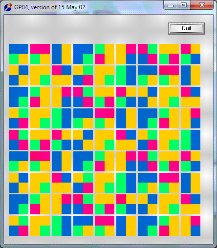
The graphic you see above was created from the program this tutorial discusses, tweaked with just a little work with Serif's PhotoPlus. PhotoPlus is an excellent photo manipulation package. A fully usable old version of PhotoPlus... which is good for drawing, too, can be obtained free from www.freeserifsoftware.com. (For more good free stuff, see my guide.) It does the things Paintshop and Photoshop do.
This tutorial will quickly re-cover the material in my introduction to drawing with Delphi. I wrote that a while ago, it may not be as well written as this, and it doesn't go as far as this one does.
Then we will draw the basis of the picture you see above. I hope you find it pretty? Along the way, you should learn something about programming elegantly from the way the picture is drawn. Incidentally... the lines in the image are all straight, despite what your brain may perceive!
Not only all of the above!!! But also!! Ta da!!....
The finished picture will carry a "secret". Coded within the picture will be....
"09 f9 11 02 9d 74 e3 5b d8 41 56 c5 63 56 88 c0"
... which is a whole 'nother story which you can explore at the Flickr 0x09F911 group.
(No, it isn't machine code, nor is it an ASCII (or near relative) encoding of anything I could find! Don't try to "break the code"... you'll be wasting your time. Yes, it is a string of hex numbers.)
This tutorial was written in May 2007, using Delphi 2, so it should work with many versions of Delphi. I played with the code again in November 2012, with Delphi 4, under Windows 7.
I have put the application's .exe and the Delphi sourcecode online for download. They are in a .zip archive.
Start a new application. Name the form GP04f1. (You don't have to use my names, but it will be simpler if you do. The name came from "Graphics Program", number four).
Add a TImage object to the form... you will find it on the 'Additional' tab of the components palette. The default name (Image1) is fine. Make it 400 wide, 400 high. (We will be playing with these dimension in our program, but these make good initial dimensions.) Set Image1's "top" to 60, and "left" to 10.
Resize and reposition the form viewer so that you can see everything easily.
Save what you have. Again, you don't have to use my names, but it will be simpler if you do.
I put everything in a folder called GP04. The .pas file was GP04u1, the project GP04.dpr.
Don't get too excited yet.. we've got a bit more work to do, if the result is going to be as good as it should be. (The details of why we need the extra hassle are in my earlier tutorial on drawing with Delphi)
Besides having the TImage component, we need to provide it with a bitmap. In your so- far- nearly- unspoilt gp04u1.pas, just after the....
private
 { Private declarations }
... add....
bmBMap:TBitMap;
We are declaring a variable, of type TBitMap, for our use in the program. I've used the somewhat ugly name "bmBmap" because "BitMap" is a name that is built into parts of Delphi, and I want the "added by us" and the "built in" elements to remain distinct.
Not only do we need to set up the name, in the case of a bitmap, we also need explicitly create it before we can use it.
Double click somewhere "neutral" on your form. Doing that should create the following empty "OnCreate" event handler....
procedure TGPf1.FormCreate(Sender: TObject);
begin

end;
Between the begin and end, insert.....
bmBmap:=TBitmap.create;
We're STILL not done. Yikes programming can be "boring".
Just before the word "type" in the sourcecode, add....
const ver='26 Nov 12';
      kbmX=400;
      kbmY=400;
The first constant won't be used by us, but designates the version of the copy of the sourcecode you are looking at. Remember to change it when old versions (ink-on-paper or machine readable) can exist which differ from the current version. We'll come back to constant "ver" in a moment in "A little bit of cleverness".
"kbmX" and "kbmY" are for "Konstant", "BMap's" "X" (and "Y") dimensions. Just putting these two lines in won't, in and of itself, do anything to or with the bitmap's dimensions.... but any and all manipulation or use of those dimensions is going to be done simply by making changes to these two lines. We'll use them in a moment, but first....
+++ A little bit of "cleverness"....
Not "necessary"... or essential to your understanding of the rest of this tutorial, but you may want to put the following inside the OnCreate event handler:
gp04f1.caption:='GP04, version of '+ver;
(It will affect what you see in the form's title bar.)
I think putting the version information in the title bar is a Good Idea. What comes next is, I think, a Bad Idea, but just so you can see that you can, try adding....
application.title:='app title';
... just after the gp04f1.caption... line. Now you'll see "app title" instead of "GP04" on your Windows taskbar. (In general, I think it is better to leave it showing the exe file's name, but you can make your own mind up... now that you know how to change the title if you want to!
.... end of "A little bit of cleverness" +++
Back to work!
Put a button on the form. Name it buQuit. Provide...
procedure Tgp04f1.buQuitClick(Sender: TObject);
begin
application.terminate;
end;
Put....
bmBmap.width:=kbmX;
bmBmap.height:=kbmY;
Image1.picture.graphic:=bmBmap;(*Assign the bitmap to the image component*)
....into your program in the OnCreate code, just after the "bmBmap:=TBitmap.create;" which is there already.
The code we've just added will remain unchanged for the rest of this tutorial. Next, just to see SOMETHING drawn, put the following in, temporarily, after the "bmBmap.height:=kbmY;"
Put the following in the form's OnCreate handler:
Image1.Picture.Bitmap.canvas.pen.color:=$888888;
Image1.Picture.Bitmap.canvas.moveto(0,0);
Image1.Picture.Bitmap.canvas.lineto(kbmX,kbmY);
(The first line isn't(?) needed in Delphi, but is helpful when trying to run this under Lazarus. (My guess? The default color, under Delphi, was "okay", but under Lazarus we are drawing in white, on white. Not relying on defaults is a good practice, in any case. Thank you http://Ruud.C64.org for altering me to this detail... and saving subsequent users the need to scratch their heads on this point. Please alert me to the other little puzzles still present in the tutorial? Save the next person?)
....and run the program. You should get a box with a diagonal line from upper left (0,0, in Windows-speak) to lower right.
Ta da! That's the basic idea!
Try changing the line that says "kbmX=400;" to "kbmX=100;". Run the program again. Notice how with ONE change in the code, we've actually accomplished at least two changes in the result? The image area is less wide, and the diagonal line is drawn to a different place.
+++ A small, unnecessary diversion. You can skip this....
Add....
var c1:byte;
... just after ...
procedure Tgp04f1.FormCreate(Sender: TObject);
... and replace....
Image1.Picture.Bitmap.canvas.moveto(0,0);
Image1.Picture.Bitmap.canvas.lineto(kbmX,kbmY);
....with....
for c1:=0 to 255 do begin
Image1.Picture.Bitmap.canvas.pen.color:=random(255)+random(255)*256+random(255)*256*256;
Image1.Picture.Bitmap.canvas.moveto(random(kbmX),random(kbmY));
Image1.Picture.Bitmap.canvas.lineto(random(kbmX),random(kbmY));
end;
... and run the program. You should get lots of multicolored lines.
.... end of "A small, unnecessary diversion." +++
That's it for setting up a "piece of paper" to draw on.
Right. For our next trick, we're going to build on what we have so far.
If you did the "small, unnecessary diversion", take out the code that was introduced for that.
If you are not comfortable with creating your own subroutines, you may want to visit tutorials on that essential skill, but give the following a try first... you should get through it anyway...
Just after....
procedure buQuitClick(Sender: TObject);
... add...
procedure Blob(iColor,iX,iY:integer);
Eventually... not just yet... that will be built into something that draws a "Blob" (a square for now), in a color determined by what is in iColor, with it's upper left corner at iX,iY.
Just before the program's final "end." (the only one followed by a "."), add....
procedure Tgp04f1.Blob(iColor,iX,iY:integer);
begin
Image1.Picture.Bitmap.canvas.pen.color:=iColor;
Image1.Picture.Bitmap.canvas.moveto(10,20);
Image1.Picture.Bitmap.canvas.lineto(50,20);
end;
... and in the OnCreate handler, just before....
gp04f1.caption:='GP04, version of '+ver;
... add....
Blob(5,0,0);
... and run the program. You should get a small horizontal line in the upper left of the drawing area.
Just before we go further, I'm going to show you what you might consider a distraction, but it will make the code a little neater. The code above can be replaced with....
begin
  with Image1.Picture.Bitmap.canvas do begin
    pen.color:=iColor;
    moveto(10,20);
    lineto(50,20);
  end;//with
end;
Get that much working.
Now, just after...
procedure Tgp04f1.Blob(iColor,iX,iY:integer);
... insert...
var c1:integer;
and, as a crude starting point, replace the "moveto" and "lineto" lines with....
for c1:=0 to 20 do begin
  moveto(10,c1+20);
  lineto(30,c1+20);
  end;
(I do realize that Delphi has a "draw rectangle" command, but why learn another, when moveto/ lineto suffices?)
That's very crude. Replace it with....
for c1:=0 to 20 do begin
  moveto(10+(iX),c1+20+(iY));
  lineto(30+(iX),c1+20+(iY));
  end;
Should give the same result... so far.... but you should be able to guess what's coming.
So far we're drawing one rectangle. Lets have a little fun....
Change...
procedure Tgp04f1.FormCreate(Sender: TObject);
var c1:byte;
...to...
procedure Tgp04f1.FormCreate(Sender: TObject);
var
 c1,bX,bY:byte;
And within that procedure, replace....
Blob(5,0,0);
... with....
for bX:=0 to 12 do
  for bY:=0 to 12 do Blob(5,bX*24,bY*24);
Nice grid of squares? Note the optical illusion: On many monitors you will see "phantom" gray squares near the corners of the black squares- at every intersection except the one you are looking at.
________
What we have so far is "okay", but it can be made better. "Better" in that it can be made more easily modified.
Just after....
private
 { Private declarations }
 bmBMap:TBitMap;
... add....
bBlobsX, bBlobsY, bBlobWidth, bBlobHeight, bMarginX, bMarginY:byte;
Then, just to get things started, in the FormCreate event handler, just after the....
bmBmap.height:=kbmY;
... add...
bMarginX:=4;bMarginY:=4;

bBlobsX:=12;
bBlobsY:=12;

bBlobWidth:=24;
bBlobHeight:=24;
... and run the program again. This should puzzle you... since the last time we ran the program we've made no changes which would affect the result... if you've entered the changes correctly!
Now make some substitutions in the program....
for bX:=0 to bBlobsX do
  for bY:=0 to bBlobsY do Blob(5,bX*(bBlobWidth+bMarginX),bY*(bBlobHeight+bMarginY));
This will make a slight difference in the results.... you can ignore it, or try to figure out the exact difference and it's source. But it is the start of changes that will bear fruits you will be shown later. Bear with me?
Now we're going to so something Bad.
In....
procedure Tgp04f1.Blob(iColor,iX,iY:integer);
... change...
moveto(10+(iX),c1+20+(iY));
lineto(30+(iX),c1+20+(iY));
... to...
moveto(10+(iX),c1+20+(iY));
lineto(10+(bBlobWidth-bMarginX)+(iX),c1+20+(iY));
This is just a start towards someplace we're going. It is Bad because we are using bBlobWidth and bMarginX, global variables, inside a procedure. In a perfect world, we wouldn't do this... but used in moderation, for reasons, it isn't so terrible.
Carrying this process of replacement further leaves us with....
procedure Tgp04f1.Blob(iColor,iX,iY:integer);
var c1,iYtmp:integer;
begin
with Image1.Picture.Bitmap.canvas do begin
pen.color:=iColor;
iYtmp:=bBlobHeight-bMarginY;
for c1:=0 to iYtmp do begin
  moveto(10+(iX),c1+iYtmp+(iY));
  lineto(10+(bBlobWidth-bMarginX)+(iX),c1+iYtmp+(iY));
  end;
end;//with
end;
About now, you're wondering "Why is this getting so complicated??"
Just a few new changes, and all will be revealed. If, before we turn to them, play a bit with the following if you like:
In the "const" section:
kbmX=400;kbmY=400;
In the FormCreate handler:
bMarginX:=4;bMarginY:=4;
bBlobsX:=12;bBlobsY:=12;
bBlobWidth:=24;bBlobHeight:=24;
_____
I have a little confession..... in moving from the nice simple, but crude, program we started with to what follows... a much better program, because of it's adaptability, I discovered some errors in the details of the simple program. While the following is very closely based on our simple program, some changes have been introduced. Let it go!
When the following is in place, you will find that you can change the values of....
bMarginX, bMarginY, bBlobsX, or
kbmX or kbmY
.... and the program adapts quite nicely, without the need for adjustments elsewhere.
Note that if you set bBlobsX or Y to, say, 5 you will get SIX blobs. This is not a mistake. It is a result of the fact that programmers count from zero.
Note also that the left and bottom margins will not always be the same size as the inter-blob gap elsewhere. It's a bit like when you did division as a child before hitting the joys of fractions. 400 divided by, say, 30 is 13... and a bit. So on a 400 pixel image, you can have 13 blobs+margins of 30 pixels each. The last margin will be too big... but 14 blobs+margin (30 pixels each) wouldn't fit, nor would 13 of 31 pixels.
Replacement code:
procedure Tgp04f1.FormCreate(Sender: TObject);
var c1,bX,bY:byte;
begin
bmBmap:=TBitmap.create;
bmBmap.width:=kbmX;
bmBmap.height:=kbmY;

bMarginX:=4;bMarginY:=4;

bBlobsX:=19;
bBlobsY:=bBlobsX;

bBlobWidth:=(kbmX-bMarginX) div (bBlobsX+1);
bBlobWidth:=bBlobWidth-bMarginX;
bBlobHeight:=(kbmY-bMarginY) div (bBlobsY+1);
bBlobHeight:=bBlobHeight-bMarginY;

Image1.picture.graphic:=bmBmap;(*Assign the bitmap to the image component*)

for bX:=0 to bBlobsX do
  for bY:=0 to bBlobsY do Blob(5,bX*(bBlobWidth+bMarginX),bY*(bBlobHeight+bMarginY));

  gp04f1.caption:='GP04, version of '+ver;
application.title:='app title';
end;

procedure Tgp04f1.Blob(iColor,iX,iY:integer);
var c1:integer;
begin
with Image1.Picture.Bitmap.canvas do begin
pen.color:=iColor;
for c1:=bMarginY to bBlobHeight+bMarginY do begin
  moveto(bMarginX+(iX),c1+(iY));
  lineto(bMarginX+(bBlobWidth)+(iX),c1+(iY));
  end;
end;//with
end;
You've been good, if you've stuck with this through that last bit, so here's your reward. Let's make that picture prettier.
We're going to change.....
do Blob(5,bX*(bBlobWidth+bMarginX),bY*(bBlobHeight+bMarginY));
"All" we're doing is replacing the 5. That makes the line...
do Blob(random(256)+random(256)*256+random(256)*256*256,bX*(bBlobWidth+bMarginX),bY*(bBlobHeight+bMarginY));
Put "randomize;" in front of the "for bX:=0 to bBlobsX do" to get different colors each time you run the program.
We're now going to "recycle" this program, retaining the shell that puts a grid of blobs on the screen, but re-working the "blobs" procedure to draw something more complicated each time. This, actually, is what set me on the road of writing this program. I wanted a novel way to display a string of 2 digit hex numbers. A 2 digit hex number, in decimal, will be 0 to 255. The first step in our conversion is to change the part of the program that calls "Blob" so that the first parameter holds 0 to 255. And change the calls of Blob so that we get a sequence of 2 digit hex numbers passed to it. The following does that.... don't worry too much about the details, unless they interest you. (It almost recreates the Basic "read"/"data" statements, if you too miss them!)
First we're going to slightly modify the FormCreate procedure... there won't be many changes, all we're doing is introducing a way to pass values to the first parameter of "Blob".... Once again, I've misused a variable (c1), using it both inside and outside of a subroutine.
procedure Tgp04f1.FormCreate(Sender: TObject);
var c1,bX,bY:byte;

function NextByte:byte;
//Note that the variable c1 is being used badly.
const data='09f911029d74e35bd84156c5635688xx'+
'00102030405060708090a0b0c0d0e0f101112131415f6f7f8f9fafbfcfdfeffxx';
var sTmp:string;
begin
sTmp:=copy(data,c1*2+1,2);
if sTmp='xx' then begin
  c1:=0;
  sTmp:=copy(data,c1*2+1,2)
  end;
sTmp:='$'+sTmp;
result:=strtoint(sTmp);
inc(c1)
end;

begin
bmBmap:=TBitmap.create;
bmBmap.width:=kbmX;
bmBmap.height:=kbmY;

bMarginX:=4;bMarginY:=4;

bBlobsX:=8;
bBlobsY:=bBlobsX;

bBlobWidth:=(kbmX-bMarginX) div (bBlobsX+1);
bBlobWidth:=bBlobWidth-bMarginX;
bBlobHeight:=(kbmY-bMarginY) div (bBlobsY+1);
bBlobHeight:=bBlobHeight-bMarginY;

Image1.picture.graphic:=bmBmap;(*Assign the bitmap to the image component*)

randomize;
c1:=0;
for bX:=0 to bBlobsX do
  for bY:=0 to bBlobsY do Blob(NextByte,bX*(bBlobWidth+bMarginX),bY*(bBlobHeight+bMarginY));

gp04f1.caption:='GP04, version of '+ver;
application.title:='app title';
end;
Now we're going to completely rework "Blob"..... Each blob is going to show a number from 0 to 255... but in a slightly unusual way!
Numbers from 0 to 255 can be shown in binary as 00000000 to 1111111, i.e. a string of 8 1s or 0s.
Break that string into four pairs of 1s and 0s. Each pair will be 00, 01, 10, or 11.
For 00, we'll use a red square, 01 green, 10 blue, and 11 black. To show 00011011, we'll put a red, green, blue and black squares together to make a bigger square....
And so to the program, built in stages, as before. First we'll create a "Bob" that always does a quadrant (subsquare) in each color, one red, one green, one blue, one black. (These are easy colors to use. More visually pleasing results can be obtained by choosing different colors.)
procedure Tgp04f1.Blob(iColor,iX,iY:integer);
  procedure SubSquare(bcolor,bx,by:byte;ixbig,iybig:integer);
  var c1:integer;
  //"bx" and "by" designate position inside bigger square. = 0 or 1
  //"ixbig", "iybig" designate position of larger square.
  const bssx=16; //Byte, SmallSquare dimension.
        bssy=bssx;
  begin
   with Image1.Picture.Bitmap.canvas do begin
    case bcolor of
      0:pen.color:=clred;
      1:pen.color:=clgreen;
      2:pen.color:=clblue;
      3:pen.color:=clblack
     else pen.color:=clteal;
    end;//case;
   for c1:=0 to bssy do begin
     moveto(ixbig+bx*bssx,iybig+by*bssy+c1);
     lineto(ixbig+bssx+bx*bssx,iybig+by*bssy+c1);
     end;//for...
  end;//with
end;//subsquare

begin //Blob

SubSquare(0,0,0,iX,iY);
SubSquare(1,1,0,iX,iY);
SubSquare(2,0,1,iX,iY);
SubSquare(3,1,1,iX,iY);

end; //Blob
From that starting point, which took no notice of the number passed to "Blob" which was suppose to determine the colors of the four quadrants, simply by declaring a few new variables, and modifying.....
begin //Blob

SubSquare(0,0,0,iX,iY);
SubSquare(1,1,0,iX,iY);
SubSquare(2,0,1,iX,iY);
SubSquare(3,1,1,iX,iY);

end; //Blob
... we can get our final result....
begin //Blob

b0:=icolor and $C0 div 64;
b1:=icolor and $30 div 16;
b2:=icolor and $C div 4;
b3:=icolor and $3;

SubSquare(b0,0,0,iX,iY);
SubSquare(b1,1,0,iX,iY);
SubSquare(b2,0,1,iX,iY);
SubSquare(b3,1,1,iX,iY);

end; //Blob
So! There you have it. The tutorial has been a bit more Bohemian than some, but there are things for many people within it. You've been shown how to set up a "blank sheet of paper" for drawing on. You've been shown a few of the most basic Delphi drawing tools. You've seen Good Practice in the use of pseudo-constants for important parameters of a project... you can "tinker" with the final result quite easily, e.g. changing the size of the blobs because the program was written as it was. And you've had a little diversion exploring alternative ways of expressing things, ways of encoding things. All for free! Please visit my freeware/ shareware pages, try something, pass it to a school????
I have put the application's .exe and the Delphi sourcecode online for download. They are in a .zip archive.
|
|
![]() Page WILL BE tested for compliance with INDUSTRY (not MS-only) standards, using the free, publicly accessible validator at validator.w3.org
Page WILL BE tested for compliance with INDUSTRY (not MS-only) standards, using the free, publicly accessible validator at validator.w3.org
....... P a g e . . . E n d s .....