Stepper motors are neat little motors which turn just the amount you require.
There's a short YouTube video showing my four coil stepper motor in action, if you want that. It is running the program discussed here, through the driver board discussed here.
Before we go further, a general point: There are at least three general types of small motors which you can control from an Arduino. I've done an overview of different low voltage, DC motors, if you want to explore the options. (The page will open in a new window or tab, just close that to come back here.
There are, for instance, the servo motors which were first used long ago in radio controlled model aircraft... They are neat too, but not the subject of this essay! (They need just one input, and are very Arduino friendly... and a little more expensive compared with what this IS about... stepper motors needing, typically, four inputs.) (If you happen to notice the word "servo" in the name of this page, imagine me blushing. That was a mistake. The page should be called "aht3FourLineStepper.htm".. but the horse had left the barn before I noticed. Sigh.)
Terry and Peng at Yourduino.com will sell you a nice little stepper motor of the sort this essay is about, with a little PCB to take care of a detail, for $4.75, plus p&p. They are available from many other sources, too.
It is not a good idea to hook up a stepper motor, even a 5v stepper motor, directly to your Arduino (or other microcontroller). There are coils in the motor, and the same problems that arise with the coils in relays arise. At least use "the relay diode". But it is Just Easier to use something like the little stepper motor driver board from Yourduino, mentioned previously. It is available separately, $2 excl p&p, Aug 2015. "All" it does is give you a way to turn four bits on and off through a small chip which protects the Arduino outputs from The Bad Things coils produce, i.e. take the place of "the diode", and allow you to power whatever the boards outputs feed separately from the power driving the Arduino. This ability to drive a power hungry device from the "weak" signal from the Arduino can be reason enough to use one of Terry and Peng's boards. (Or similar from someone else.)
That little driver board is a great device, useful for many things apart from driving stepper motors! (It has four bits, and each can be used independently.)
You would probably "get away" with using the 5v generated by the 5v source created on your Arduino to power ONE of the Yourduino stepper motors. I did, using an Arduino Pro Mini. But if you can find 5v somewhere else, it would be better, and I would certainly Find A Way, if I was driving more than one stepper motor, or doing more than just Seeing If I Can Make It Work.
Forgive a slight digression? If you have no interest in a few paragraphs about something to make using Arduinos easier for the novice, and to protect the Arduino from the novice, you can use this link to skip ahead.
... but only if you use the twelve way connector.
NoviceGuard is a little PCB I have created to help novices get started with Arduinos. Besides helping the novice, the board protects the Arduino from some novice mistakes. I have "run" a stepper motor through a NoviceGuard.
The best way to use the twelve way connector has not yet been fully developed.
For use with NoviceGuard, for the moment, I am recommending that you connect the four inputs to the motor, through a suitable interface (such as the one from Yourduino) to pins 9, 8, 7 and 6 of the Arduino. Doing that will mean that in the Arduino code, you need...
When the NoviceGuard library, NovGrdCore, has been expanded, to offer twelve way connector support, there will probably be mnemonic names for those pins.
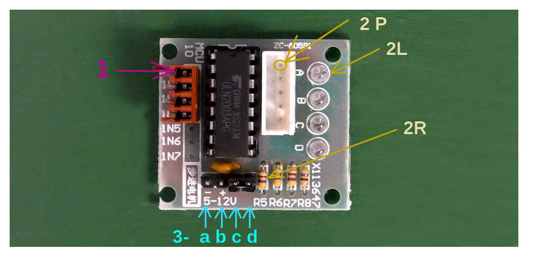
What have we got?
At "1", over at the left, the first of four pins in a column. This is where you connect the outputs from your Arduino or other electronics.
At 2P, the pin where the output appears. Again, it is the top one in a column of four circuits that are just "copies" of one another.
At 2L, an LED that lights when 2P is high.
At 2R, the resistor which is in series with the LED.
At "3", the fun begins. Refer also to the circuit diagram.
I don't think that the board designers have not given us a way to keep the grounds of the "Arduino" and "Driven outputs" sides of the board's circuits separate. A pity, I think, but there you are. Maybe not possible, but I want to think on that one for a bit! (^_^). (Keeping the two sides of something like this separate IS possible... easy... if you use opto isolators, aka opto couplers.)
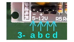
To hook up power correctly, put the ground for the Arduino AND for whatever you are driving, the stepper motor motor's coils, in the context of this discussion, but the board is great for any general bit- by- bit driving needs.... as I was saying... hook up the TWO grounds to pin 3a.
Supply 5v to pin 3b.
Connect the link between 3c and 3d.
(This isn't the only way this board can be set up, but if you use a different voltage on the "Driven outputs" side, the right hand side, as the photos are oriented, you have to change the LEDs' resistors for a start.)
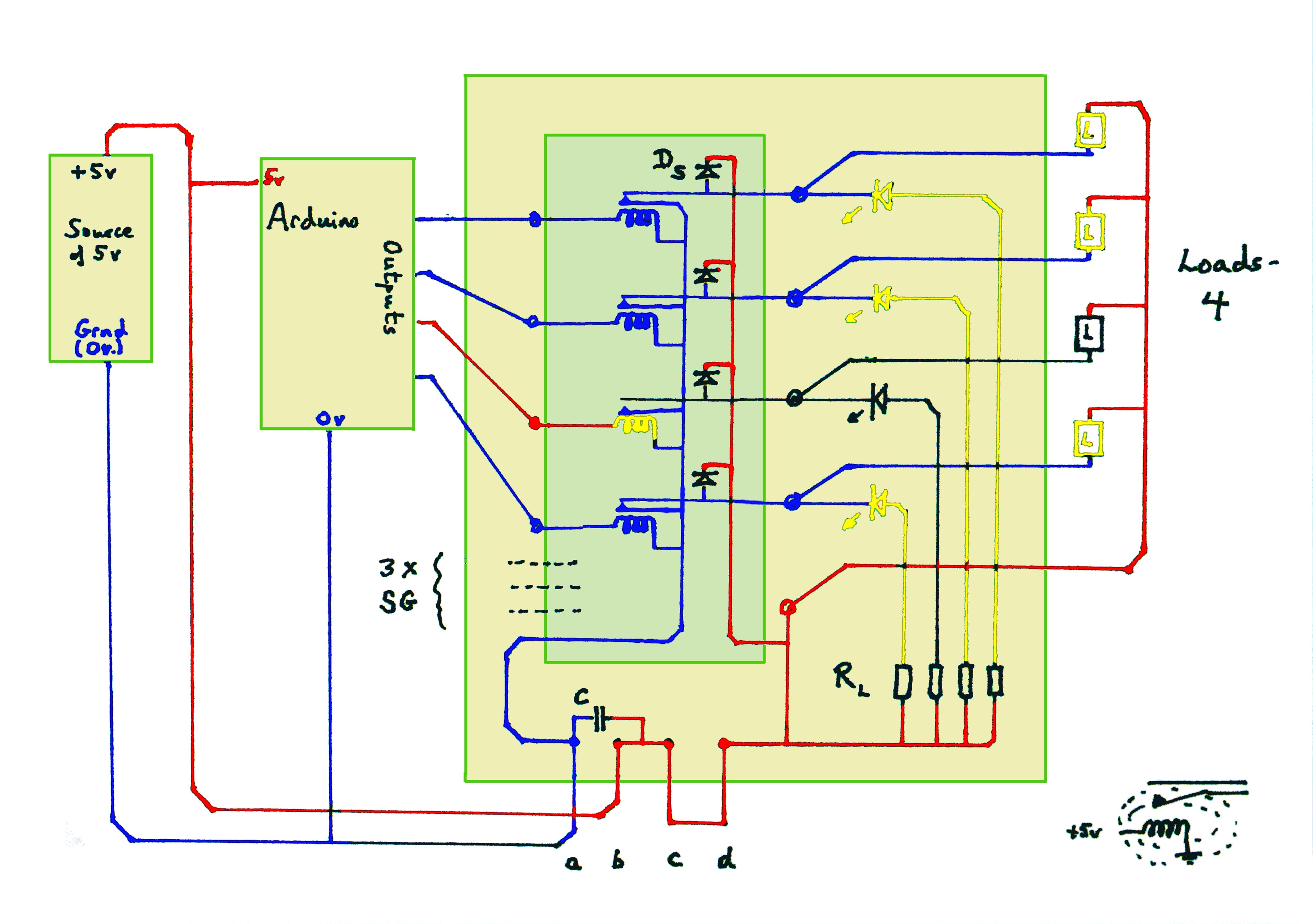
I hope what is above already lets you "just use it". For those, like me, who obsess about just exactly what is going on, here's a "tour" of the circuit diagram.
THE BOARD DOES NOT USE RELAYS!
I hope my diagram hasn't confused anyone. I've shown relays, because they are easier to understand than the gates which are what is actually inside the chip on the PCB. (A ULN2003APG)
These "relays" are normally CLOSED. (That is what the little sketch at the lower right is trying to say. The dotted lines are the magnetic field emanating from the energized coil, pulling the relay contacts APART.)
There would, if the circuit was really based on relays, be extra diodes on the coil side of the circuit.
I keep talking about the "sides" of the circuit.
Just in case what I mean isn't obvious, a little sidebar...
The stepper motor driver board I am describing is actually a very generally useful board. (Thank you Arduino forum Grumpy_Mike for pointing that out years ago.)
It offers four channels you can use independently. On one "side" of the circuit (to the left, above), there is an input... one that is Arduino (and Pic and Stamp, etc) friendly. You connect that to an output from the microcontroller. Only a small current flows through the microcontroller's pin to make the input (of the controlled circuit) high or low.
When the input to the driver board's circuit is LOW, current will flow into the driver board's output pin for that channel, if a voltage is present.
That's why, on the connector for the driver board, there is a pin carrying 5v. See diagram.... you have 5v from the board, to the "thing" you want to turn on and off (represented in the diagram as the four boxes marked "L", for "load"). IF the input to a channel (the left "side" of the circuit) is connected to an output from the Arduino which is LOW, then current will flow on the right hand "side" of the driver board circuits, the thing you want to turn on will come on.
The currents in the right hand side of the board can be quite high without the currents on the left hand side (through the Arduino output) being high.
Those are the two "sides" of the driver board circuits... and quite a bit about why we have them!
In the diagram, I have shown three of the four channels being fed a "low" from the Arduino. The third from the top I have shown being fed with a "high" from the Arduino.
The result of these outputs from the Arduino is also represented in the diagram. The third (from top) load is shown in black to represent it being "off". The others are "on".
The LEDs on the driver board go on when the input to the board for the corresponding channel is low.
The 5 way connector that provides the outputs from the driver board to the "driven" devices, on the right in the diagram, provides one pin for each device, AND a pin for whatever voltage you have provided to the right hand side of the board.
The simple "answer" is to connect the power connectors c and d ("3c" and "3d" in the earlier photos) with a link, thus "passing on" the 5v used to power the IC on the driver board. You must, of course, be sure that the source of 5v you are using is adequate. Is it rated to deliver all of the mA (current) that your load(s) will call for?
Your alternative is to use a different source of power for the right hand side of the driver board and the loads.
To take this approach, remove the jumper between c and d. Feed in the positive side of the new voltage through pin d, and connect the "negative", or ground, or "zero volts" side of the new power source to pin a of the driver board. (Or some point connected directly to pin a... any bit of the board shown in blue in the diagram.
You could, in fact, supply the right hand side of the board with something other than 5v. You would, however, need to change the resistors for the LEDs (RL) if you changed the voltage significantly.
I will try to get back to this later, tell you more.
In what follows, we will connect the four inputs to the motor, through a suitable interface (such as the one from Yourduino) to pins 9, 8, 7 and 6 of the Arduino. Unless you are using a NoviceGuard, you can use any four digital outputs. (Even with NoviceGuard, some flexibility is possible.) But once you've chosen the pins you want to use, be sure to change the....
Stepper small_stepper(STEPS_PER_MOTOR_REVOLUTION, 9,8,7,6);
... line in the code!
Connect the grounds of the Arduino, the stepper motor driver board, and the stepper motor.
Supply the motor with 5v. (Assuming you are using a 5v motor! Other voltages are possible, if you know what you are doing.) If you are running just one motor, and "just playing" with it, then you can probably tap into the 5v pin from your Arduino... but it would be better to power it from a separate source of 5v. With USB chargers so easy to come by, I would use one of those, at least. Remember to connect the grounds of the two power supplies. The driver board does not separate the grounds of the two sides of the circuit. It does, however, provide suitable "snubber" diodes to take care of reverse emf from the motor coils.
Much of the following comes from the excellent tutorial at Yourduino's tutorial collection, Arduino-Info.info. (The link takes you straight to the one drawn upon.)
There is just one little "gotcha" in the following... well, got me. I'll explain in a moment. The code causes the shaft of the motor to rotate 360° in one direction, and then 360° in the other direction, and those two rotations get repeated over and over again. I'll provide some comments on the sketch later.
/* YourDuino.com Example Software Sketch
   ------------------------
   (SLIGHTLY MODIFIED by TK Boyd, 17 Aug 15, for the
   purposes of...
   http://sheepdogguides.com/arduino/ah3fourLineServo.htm
   (The only change was in the line "Stepper small_stepper(STEPS...".
    and in how the stepper motor was hooked up to the Arduino.)
   ------------------------

   Small Stepper Motor and Driver V1.4 11/30/2013
   http://arduino-direct.com/sunshop/index.php?l=product_detail&p=126
   Steps one revolution of output shaft, then back
   terry@yourduino.com */

/*-----( Import needed libraries )-----*/
#include <Stepper.h> //this is a "standard" library, comes
    //with the Arduino IDE. From at least vers 1.0.6

/*-----( Declare Constants, Pin Numbers )-----*/
//---( Number of steps per revolution of INTERNAL motor in 4-step mode )---
#define STEPS_PER_MOTOR_REVOLUTION 32

//---( Steps per OUTPUT SHAFT of gear reduction )---
#define STEPS_PER_OUTPUT_REVOLUTION 32 * 64  //2048


/*-----( Declare objects )-----*/
// create an instance of the stepper class, specifying
// the number of steps of the motor and the pins it's
// attached to

//The pin connections need to be 4 pins connected to
// Motor Driver In1, In2, In3, In4  and then the pins entered
// here in the sequence 1-3-2-4 for proper sequencing

//**N.B. NEXT LINE CHANGED by TKB FROM
//    ARDIUINI-INFO.INFO ORIGINAL
//**.... but just to use different Arduino outputs...
Stepper small_stepper(STEPS_PER_MOTOR_REVOLUTION, 9,8,7,6);

/*-----( Declare Global Variable )-----*/
int  Steps2Take;

void setup()   /*----( SETUP: RUNS ONCE )----*/
{
// Nothing  (Stepper Library sets pins as outputs)
}/*--(end setup )---*/

void loop()   /*----( LOOP: RUNS CONSTANTLY )----*/
{
  Steps2Take  =  STEPS_PER_OUTPUT_REVOLUTION ;  // Rotate CW 1 turn
  small_stepper.setSpeed(500);
  small_stepper.step(Steps2Take);
  delay(1000);

  Steps2Take  =  - STEPS_PER_OUTPUT_REVOLUTION;  // Rotate CCW 1 turn
  small_stepper.setSpeed(500);  // 700 a good max speed??
  small_stepper.step(Steps2Take);
  delay(2000);

}/* --(end main loop )-- */
There is more to come on this topic... But I'm out of time, and thought you'd want what's done so far?
With all work with this sort of stepper motor, there is a little "gotcha" to watch out for...
At the heart of how these motors work is the fact that there are magnetic coils inside them, and each gets pulsed with electricity in a sequence.
The software does a good job of generating pulses for the separate coils, with the proper timings, etc... but if you hook up the outputs from the Arduino in the wrong sequence, the motor is not going to work well!
With the board from Yourduino and the software cited above, the Arduino pin connections need to have 4 pins connected to Motor Driver In1, In2, In3, In4 and then the pins entered in the software in the sequence 1-3-2-4 for proper sequencing.
If you have the wires connected in the wrong sequence, the motor won't turn smoothly; it may not turn at all. But I don't think you'll do it much harm, operating it thus for short spells.
The nice people at Yourduino not only sell Good Stuff, at reasonable prices, they also tell you how to hook it up. Much of the above comes from the Yourduino curated Arduino-info.Wikispaces.com page about small stepper motors. I hope you will feel that I have added a bit to it, made parts accessible to a different audience... but my thanks to Yourduino, none-the-less!
The search engine merely looks for the words you type, so....
* Spell them properly.
* Don't bother with "How do I get rich?" That will merely return pages with "how", "do", "I"....
Please also note that I have two other sites, and that this search will not include them. They have their own search buttons.
My site at Arunet.
My Sheepdog Software pages, another of this page's editor's sites.
![]() Page has been tested for compliance with INDUSTRY (not MS-only) standards, using the free, publicly accessible validator at validator.w3.org. Mostly passes.
Page has been tested for compliance with INDUSTRY (not MS-only) standards, using the free, publicly accessible validator at validator.w3.org. Mostly passes.
AND passes...
