This page is still quite "raw". But may be enough to enable you to get started, using the Maxim/ Dallas 1-Wire chips (via the TMEX support SDK) with Lazarus. It also has a general introduction to how 1-Wire works.
If you are already experienced with 1-Wire, and have a little Lazarus (or Delphi) fluency, you should probably just skip straight to...
Part Two, Using 1-Wire/ MicroLans/ TMEX with Lazarus
But, for those wanting more help, this has everything you need to start from scratch and get to where you can read a DS18B20 1-Wire chip over a MicroLan, using Lazarus. (Apologies, one last time, for the poor quality, so far, of the supporting text.)
And there is a free zip archive with the sourcecode!
The page you are reading, so far, is a pretty poor dog's dinner. But the software you can download from here is not rubbish. Download it. Play with that. Only resort to the tutorial below if desperate! It starts with a long introduction to what MicroLans are, why they are cool. I suspect you already know. Skip over the general introduction to 1-Wire, if you wish, to how to use 1-Wire under Lazarus. (Non-Lazarus readers may be better served by my more general index to Maxim/ Dallas 1-Wire matters. And there's a page specific to Arduino/ Pi users who want to use Maxim/ Dallas 1-Wire chips.
I used 1-Wire with Delphi for many years, so was disappointed when Borland/ Embarcardo/ whatever they are called this week shut the hobbyist out of Delphi... and proportionately delighted when Lazarus came along. I've been using it for some time now, no regrets.
So the day came when I wanted to "do" 1-Wire... from Lazarus!
1-Wire isn't for the faint hearted... but it WILL reward you, if you make the effort.
You will need some code supplied (free) by Dallas. "Drivers". An SDK. Etc. (Dalsemi/ Maxim... whatever THEY are called this week.)
In particular, you need some code which started as a unit for Delphi. Happily, it works with Lazarus... if you poke one simple little line into it. (Lazarus is virtually an open source Delphi. LOTS of Delphi stuff works with Lazarus. Hurrah. Thank you, coders. And Borland, for creating the initial model.)
The code is in iBTMEXPW.pas.
To use it with Lazarus, the simple (if clumsy and inefficient) way is to put a copy of it in each project's main folder, i.e. the folder with the app's main unit's .pas file.
AND, TO iBTMEXPW.pas, ADD....
{$mode delphi}//Added by ((insert your name))
... right at the top, just after the "Unit iBTMEXPW;" line.
(You don't... why would you? (But given that I wondered, maybe you will)... need to put the {$mode delphi} into anything else needed by this.)
This tutorial has two main parts. The first attempts to describe the basic idea behind the Dallas 1-Wire/ MicroLan. (And explains what those terms refer to, along the way!). The second goes into detail about wiring up MicroLans and writing software for them.
If you think this starts slowly, fine. Skim that material. It gets "hard" pretty quickly.
In a moment, I will be using what I will call an "LED/resistor unit".
That's just an LED soldered to a suitable resistor in series. I've only invented "LED/resistor unit" to save saying "LED soldered to a suitable resistor in series" repeatedly!
(Note to self:... qInsert circuit diagram, and TKB symbol "tkbLRU")
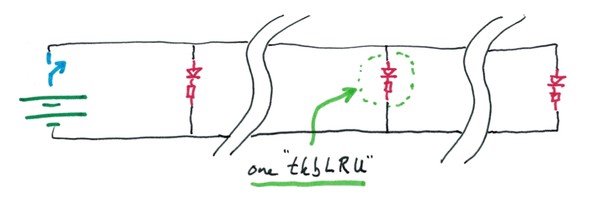
Terminology: a "parallel circuit" with 3 LED/resistor units looks like this...
------------------------------
         |          |         |
      tkbLRU1    tkbLRU2   tkbLRU3
         |          |         |
------------------------------
(qBetter illustration to come)
I think of it as a ladder, with the two long wires the side rails, and the tkbLRU the rungs. (Ladder laid horizontal.)
But! None of those LEDs would be lit up. You need a battery for that. We'll also add a switch while we're at it. Switch open, all LEDs off. Switch closed, all LEDs on.
(The battery/ switch "rung" is another element connected up "in parallel with" the elements we had before.)
In theory (though not quite so simply in practice, although the principles wouldn't change) you could make the wires really long. Let's, for the moment, imagine 5 miles between LEDs.
ILLUSTRATION TO COME
The squiggly lines in the new diagram above are used to say "long piece of wire here".
If you trained some people in Morse code, and paid them to sit watching the LEDs, you could send messages...
FROM: Where the switch is....
TO: Where all of the people watching the LEDs.
So far, so crude. Fear not, MicroLans are much more capable! Each place equivalent to...
the battery/ switch... or
a LED/ resistor unit
...can receive and send messages, for a start.
===So far we have a string of units, wired together in parallel.
I said things would get harder in a moment. Here we go....
Circuit diagram of shortable system...
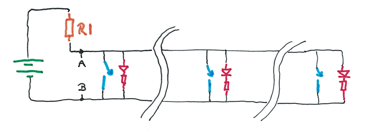
(Before I continue the discussion, let me just say something to those who will look at the above and say it is a "bad circuit": Yes. I know. But it would work... if carefully tuned. It is only a step along our way. Don't worry.)
In the circuit above, I have removed the "turn all LRUs on/off" switch. (Disconnect the battery some other way, or add a switch not shown, if you want the circuit to have a way to turn everything off when you don't need it running, and want to save your battery.)
With none of the new switches closed, all of the LEDs will be lit.
Here's what happens when any switch is closed...
Now there is a low resistance path between the two "rails".
This causes the current flowing through R1 to increase. It would become bad-for-your-battery large unless R1 is well chosen. R1 will need to be quite resistive. But it will need to be low enough for...
When a large-ish current flows through a large resistor, you get a big voltage drop.
If you had "the right" R1, and the LED/resistor units had "the right" properties, these are voltages you might see...
The voltage "across" the battery would be the same, whether any of the switches across the rails were closed or not. That's just how these things work.
When none of the switches were closed, some current would flow through R1. With three tkbLRUs in parallel across the rails "fed" by the "bottom end" of R1, through R1 you would get three times the current flowing through one of the tkbLRUs.
If some current is flowing through R1, you will get some voltage drop. In my diagram, I have assumed a 12v battery, and a 2v voltage drop across R1 when it "feeds" three tkbLRUs.
I would have chosen LEDs and resistors to go with them in the tkbLRUs which were "happy" with the current that would flow if they were subjected to 10v. Would be happy, and would glow nicely.
Now... what happens if someone closes one of the switches?
Now there is virtually NO resistance between the points I've marked "A" and "B". And so more current (than before) flows through R1. And if more current flows, there will be a greater voltage drop. Now the voltage drop across R1 is 10v, and there's only 2v "left" between "A" and "B".... and the LEDs were chosen to be ones that don't glow with only 2v across then.
Closing any of the switches will turn all of the LEDs off!
This really is cool, even if that hasn't struck you yet. And it really could be made to work, although getting the value of R1 right could be a little tricky, and if you wanted to add another LED/resistor unit, you'd have to match the ones you'd used previously, and you'd have to use a different resistor at R1. Tedious.
Too BIG a resistor at R1, and the LEDs won't come on, even when only the main "on/off" switch (SW1) is closed. Too SMALL a resistor at R1 and the LEDs won't go off, and you might even have trouble with the battery going flat very quickly (or the PSU being damaged).
But the circuit would work, if you knew how to get the sizes of the resistors right.
Happily, you won't have to worry about any of that, because the Dallas engineers took care of those things when they designed the 1-Wire/ MicroLan system... which works along the lines of the system described above, as i will explain.
Going back to the system we've been talking about...
Now we have a set of LEDs, widely separated, and a switch beside each one.
If any switch is closed, all of the LEDs go off. So now we have a system where, if you had a person trained in Morse code at each LED, you can send messages FROM any station TO all of the other stations.
One little problem: If two people "try to talk at once" the LEDs will be off whenever EITHER of them has his switch closed. And the pattern of ons and offs on the LEDs would be meaningless. No big deal. The Dallas engineers thought of that. But it IS something than NEEDED thinking about.
One last thing to notice about this simple little system we have built up for sending messages back and forth over some long wires: There's only one battery/ voltage source. We don't need one at each of the places we have a LED/resistor unit plus switch.
====Onward!
Now we come to the Maxim (formerly Dallas) 1-Wire chips, and MicroLans.
Dallas is the company that first created the chips.
"1-Wire" is a trademarked brand name. Only Dallas can sell something called "1-Wire". All of the things they sell under that name share sundry properties, and play nicely together.
Every 1-Wire device has at least two connection points. Sound familiar? Remember the little units we connected to the "rails" of our "ladder"...
ILLUSTRATION TO COME
There are many chips in the 1-Wire family. There are none exactly like our LED/ resistor + switch units, alas... but we can accomplish what they accomplish. It just isn't quite as easy. However one very popular 1-Wire chip does something that we could never do in our simple circuit... it can send messages across the MicroLan about the temperature around it.
There are actually several 1-Wire temperature sensors. They differ in the range they can sense, the precision they offer, etc. In this, I will use the DS18B20 as my example. The others work along the same lines.
I am also going to introduce you to the ((one bit input)) and ((one bit output)) chips.
When you connect one or more 1-Wire chips to a pair of wires, making a "ladder", you have created a MicroLan!
Here's an over-simplified MicroLan circuit...
ILLUSTRATION TO COME
((Sidebar:)) 1-Wire chips, in particular the temperature sensors, are very popular with the Arduino and Pi crowds. They tend to use them in a perfectly acceptable, but rather limited manner. I'll leave how that's done for another time.
((END OF Sidebar))
You've had a taste of my normal tutorial writing style.
For a bit, here, I am going to try to shift gear, and move more rapidly.
The best way to get started with 1-Wire is to use the software Maxim gives away with the SDK.
You'll need, to get started...
You will... in a moment... hook them up like this...
ILLUSTRATION TO COME
Dallas made it easy for people with little hardware experience to connect 1-Wire chips to their PCs. They produced "adapters" to do the hard work of connecting a MicroLan to a PC.
There are several different adapters on the market. In the old days, you could connect one via the parallel port or via a serial port, and Just Use the MicroLan without having to do very much at all to reflect what sort of adapter you were using. You did... and still do... have to pay a little attention to that detail, but Dallas made everything easy.
Today, I suspect most people use an adapter that plugs into the PC via a USB socket. On the "other side" of the adapter, there is a way to connect two wires.... the two wires which were the "sidebars" of the "ladders" in my introduction to MicroLans.
((Maybe more needs to be said? About role? Actual hook up?))
Read on before plugging in your adapter. So far we've only looked at what one is.
Start with one of the temperature sensors. I'm using a DS18B20 in the example here. It would only take a small tweak to "fix" the code to accept whatever temperature sensor chip has "$10" for its family code. (You do the same things, in 1-Wire terms. The difference is in how you interpret the two bytes of data the system will give you from the temperature sensing chip.)
Before your hardware will be of use, you need to download the SDK from Maxim, install it.
That will give you what you need for writing programs which access MicroLans. It will also give you a little utility called "One Wire Viewer".
Install all of that. You don't need, and should not (yet) plug in your adapter to get the software installed. Under Windows XP, you are left with 2 new folders in the start menu, "1-Wire Drivers x86" and "1-Wire TMEX SDK". And a link to some "TMEX API Help". (TMEX is the software associated with the 1-wire chips and MicroLans.)
"1-Wire Drivers x86" holds more than just drivers.
Inside "1-Wire Drivers x86" you should see (don't click on it yet) "Shortcut to OneWireViewer"
If all's gone well, you have the core software in place. Now...
Now plug in your adapter. If it connects to the PC via USB, and you haven't plugged it into this PC before, you'll probably have it ask for permission to go off to the internet, fetch a driver. Allow this.
Now plug a 1-Wire chip into the adapter. Most use (US) "telephone" style connectors. One of the conductors should carry 5v relative to one of the others, and these will probably be the "inner" two conductors of the "telephone" connector's 4 conductors.
The one that reads "0v" is your ground. The other is called various things... it is BOTH the wire across which the MicroLan's data flows AND (often) the wire which carries the electricity the 1-Wire chips need to operate. More on this anon.
If you don't have "made up" cables, so you can just plug your 1-Wire chip into your adapter, here's what you need to know, if using a DS18B20...
Fetch the chip's datasheet. You need to start getting your head around these. You don't need to understand all of it, but the diagram which names the pins is needed now.
Connect the pin helpfully called "GND" (for "ground") to the "zero volt" wire from the adapter we spoke of earlier.
Connect the pin called "DQ" (on the data sheet) to the wire with 5v in it.
Connect the third pin, called Vdd, to the pin called GND. (This may seem odd. Some of you will know that Vdd is usually the voltage to run the chip comes in. Not in this case; not in this configuration. You can connect 5v to Vdd, and power the chip that way. But for now, in our simple scenario, we are going to use "parasitic power".. and we "say" "we are using parasitic power by this shorting of the Vdd pin to ground.)
Right! That's the connecting done. With your adapter plugged in, and a 1-Wire chip connected to it, launch OneWireViewer.
The first time you launch OneWireViewer, you'll first pass through a little utility to make settings in OneWireViewer about what type of adapter you are using, and "where" it is. (Which port, if using a serial port.)
((Had to fiddle about a bit.))
(Kept getting MicroLan Not Avail text)
Finally got working
Essential to harvest Dallas ID (explain) of chip using...
28 E3 D9 34 01 00 00 2E
Good to confirm chip type... indicated by final byte, too, though. (DS18B20)
Ensure working...
Select the tture chip, then the "temperature" tab. A graph should begin building immediately, and grasping sensor with warm fingers, or putting to warm tongue should show immediate warming of sensor.
Close 1-Wire Viewer.
Using the Dallas-supplied small utility "Default 1-Wire Net.exe" allows you to see how the adapter had to be set up to get it working. Don't be puzzled if you see "PC Port Type: COM" if using a DS9790. The 9790 creates a "virtual" serial port, using the USB channel. Note that you will have had to specify a "Port number". Which should you use? I don't know. Zero didn't work for me, 1 did. Will it be stable? I don't know. It seems to be, on a machine where not much is going on, in the way of changes to what's hooked up to it.
===
I'm now going to present a Very Crude example of programming a computer to access a MicroLan. The crudeness is mostly in the program's almost total inability to deal elegantly with any "little problems." It also has several things hard-coded into it, such as the Dallas ID of the chip it will read. But I've written the program with a view to making it better.
I present the crude version first, to give you as few distractions as possible, so you can see the heart of what has to happen.
Before any of this will work, you need to have installed the Maxim/ Dallas TMEX SDK.
===
The program does have one or two little "frills". It doesn't use Showmessage. Any "messages" get appended to all previous messages in a memo. I have done it this way so that the program can run automatically, and not need interaction with an operator.
The iButton ((define)) TMEX API Help file is extremely useful, once you learn your way around it. And don't worry... you only need a handful of the subroutines provided.
===
Building our Lazarus ((I haven't explained that's what I am using, or why)) application:
Start a new application. Assign a good "root" name, I used LDN030 (30th Lazarus Demo in the New series)
Create a folder for the work to reside in. I called mine "LDN030- Simple 1-Wire Read Tture".
Add "iBTMEXPW" to the "uses" clause.
Put a copy of iBTMEXPW.pas in the application's folder. ((WHERE TO GET IT... mine was in a DELPHI folder... rather ancient!)) ((EXPLAIN WHAT IT IS, why we want it. EXPLAIN THE TWEAK: {$mode delphi}//Added by TKB... just before "Interface". EXPLAIN HOW users only need the .o in lib/i386-win32... IF they need that.))
You "connect" by calling the TMExtendedStartSession function. You might think of it as "getting a dial tone" in terms of old fashioned "wired" telephony. (Don't be worried by the "Extended" in the name, TMExtendedStartSession. It is just an improved TMStartSession, which no one uses any more.)
It returns a number. If the number is 0 or negative, it signifies a problem. (We'll get into dealing with those cases eventually, perhaps. For now, we'll assume an number greater than zero.) The returned number (if greater than zero) is called your "session_handle". We'll be using it quite a lot in what follows.
Eventually, you should call TMEndSession. Along the way, from time to time, you may want to call TMValidSession to see if your session is still valid, still "connected"
It is via the "session" that you do everything else that you do with the 1-Wire chips on the MicroLan.
Beware: The terminology in respect of data types in the TMEX documentation is sometimes at odds with the way similar names are assigned in the Lazarus world. Look closely at how many bits are involved, and at whether the type is signed or unsigned.
The TMEX help says...
long far pascal TMExtendedStartSession(

short PortNum,			// Port number to get a session to
short AdapterType,			// Port type number to get a session to
void far *Reserved			// Reserved pointer (should be NULL)

);
.. and elsewhere in the help file we find... (snipped)...
General Types

short		16 bit signed integer
long		32 bit signed integer
far pascal		far function using pascal calling convention
void far *		generic far pointer
Thus, under Lazarus we would use that as follows....
First, we'd need variables. I've chosen names for these as follows. The declaration of these variables has been put in the public block of the declaration of the Tldn030f1 class... I've made them as generally available to the application as possible.
  liSessHdl:longint;//32-bits, treated as a a signed integer (negative 2 billion or so (10 to the power 9) to positive 2 billion or so)

 siPortNum, siAdapterType:smallint;//16-bits, treated as
        //a signed integer (-32768 to +32767) ((DON'T
        //CONFUSE "smallint" and "shortint"!
Confession: I know little about pointers. "myPointer" is a kludge... but one that I make with some confidence. The parameter is something that is just a placeholder, something Dallas put in, reserved for future use. I don't believe that use has yet arisen, so what's happening around this parameter is not of great consequence, as long as it is contained.
Once those are available, we can execute the following code. I put it in the FormCreate handler in this, our crude version of reading the DS18B20 temperature sensor.
 siAdapterType:=6;
 siPortNum:=1;

 liSessHdl:=
    TMExtendedStartSession(siPortNum,
       siAdapterType,nil);
===
The value returned in liSessHdl will fall into one of three categories... You can (and should) read about this in the entry for TMExtendedStartSession in the TMEX API, which comes with the 1-Wire download.
If it is >0 then it is a valid session handle. We are "connected" to the "stuff" in the TMEX software that we want to connect to, and can now go on, do what we came here for. At the end of everything, we should "disconnect" with a call to TMEndSession. ((DEAL WITH THIS!))
If after calling the function, we find zero in liSessHdl, that tells us that the port was not available, it was being used by another application, perhaps?
If after calling the function, liSessHdl holds a negative number, we have an error. In general, the TMEX API Help file (and the code in iBTMEXPW.pas) gives the details of error codes for all of the various functions built into the support unit. One day you will want to learn more about them, provide options to the user of the software based on what the error was.
In the case of a call of TMExtendedStartSession, the defined error codes are only...
(-200)   INVALID_SESSION -  session not valid
(-201)   HS_NOT_FOUND -  Hardware_Specific driver not found and is required
The most likely reason for an error here is that either the adapter type or port number you supplied to the function wasn't right for your hardware. ((FINDING ADAPTER TYPE))
For now, in this "get you started" code, a crude answer:
Set up a global variable boSessionValid, type boolean. And make all of FormActivate...
  //Port Type: Use 6 for a DS9490R#
  siAdapterType:=6;//These 2 to be moved to better place
  siPortNum:=1;//and provided with better "fill" mechanism

  boSessionValid:=true;

  liSessHdl:=
     TMExtendedStartSession(siPortNum,
        siAdapterType,myPointer);

  if liSessHdl<=0 then begin
     boSessionValid:=false;
     showmessage('Call of TMExtendedStartSession failed. '+
       'Shutting down.');
     close;
     end;
Crude, as I said. But once you get the right values into siAdapterType and siPortNum, we'll be able to get on with a quick romp through the main elements of using 1-Wire chips. And, because I've fought with these things before, I have a bigger plan in mind, I hope you will find that our "start" "cleans up" into something more respectable quite well. (As things stand at the moment, boSessionValid doesn't do much. It's one of the little bits that I will put in here and there to make expanding this successfully easier.)
Create a global smallint siTmp, and add the following FormClose handler...
procedure Tldn030f1.FormClose(Sender: TObject; var CloseAction: TCloseAction);
begin
   if boSessionValid then begin
     siTmp:=TMEndSession(liSessHdl);
     //This does return error codes, which, eventually, should be
     //   looked at, dealt with.
     //We may pass through here when liSessHdl is no longer valid,
     //   but we didn't know that, and haven't had a chance to
     //   change boSessionValid to false. boSessionValid is still
     //   useful, for saving us going into things that need a handle
     //   when we DO know that the session handle is no longer valid.
     end;
end;//FormClose
Ta da!! We've made a start!
What comes next may give you a headache... but in some respects, the hard parts are behind us!!
This is a moment to take a break from writing code to go back and look at basic concepts I have, so far, spared you.
First the good news: There is a reason for the complex ideas to come. It is that without them, you'd have a real problem hooking up multiple 1-Wire chips, even "just" a few temperature sensors, using just two wires.
Sidebar: Why did they call it "1-Wire" when it takes TWO wires? Well, one of those two wires is "just" the ground wire, the return path which completes the circuit the electrons flow around. Electronics engineers "just know" that you always have a ground wire. Many circuit diagrams barely show the ground wire. Our circuit....
ILLUSTRATION TO COME
... would make perfect sense to an electronics engineer drawn like this...
ILLUSTRATION TO COME
(end of sidebar)
So... how do you get even three temperature sensors to play nicely across just two wires?
The master is going to "say" to each of them in turn, "Take a reading. Tell me what you saw."
It's a bit like an old fashioned school classroom. The teacher sat at the front. He/ she decided who would speak when. Children spoke when they were told to, and not otherwise. The air in the room was like the "one" wire in the Dallas 1-Wire/ MicroLan system.
Remember our early circuit, where there was an LED/resistor unit and a switch at each "node" along the long wires? And any of the switches could turn ALL of the LEDs off?
MicroLans work a bit like that. Each 1-Wire chip wired to the MicroLan is one node. As long as no more than one of them ever closes its "switch", the messages (coded by moments of the voltage in the "top" wire going down to zero) in the wire will make sense.
The master device on the MicroLan dictates who speaks when... like the old fashioned school teacher.
Here, in detail, is how that is managed....
EVERY 1-Wire chip behaves the same... up to a point. Beyond that, they each have special "powers"... for instance, we will eventually look at 1-Wire chips which are temperature sensors. They have no inputs or outputs, apart from their "standard" connection to the MicroLan. We will then look at a chip with an extra pin, an output, which can be made high or low by commands over the MicroLan from the master. And lastly, we will look at a chip with an extra pin which is an digital input, which the master can "look at". (There are many other 1-Wire chips, each with their own powers.)
One other thing you need to know about 1-Wire chips.... ((THEIR ID))
A moment ago, I said that every 1-Wire chip behaves the same, up to a point.
By the way... think of them as pre-programmed little microprocessors... each one is rather clever. Here is how they behave...
When a MicroLan first receives power, the chips "wake up" in a "standing by" state. They sit there, watching the state of the data line.((SAY WHAT YOU MEAN BY "DATA LINE"... first use))
In a properly set up MicroLan, there is one master device, and one or many slaves.
Until the master "speaks", everyone will remain silent. A few chips may be "doing things", but they won't "talk" to the MicroLan... they won't "press the switch" which pulls the data line low. (And example of a "doing things" chip: There are 1-Wire chips which can keep track of TimeOfDay, i.e. hh:mm:ss.)
Sometimes things go wrong. Whether it is to finish a planned task, or to recover from something that shouldn't have happened, all of the chips are made so that if the data line goes low for a long time (a very precisely defined "long time", of course, but for our purposes, "long time " will do)... if the data line goes low for a "long time", then all of the chips reset themselves to the "waiting to hear from the master" state.
This, unremarkably, is called "doing a reset", and the function you call, to make the master pull the data line low for the right period is TMTouchReset
Now we come to the really, really clever bit of the whole thing:
There's another call, TMAccess,((has built in TMReset)) ((Doesn't ensure device is present. Strong access does... but takes 3x as long))
One of the parameters of TMAccess is filled with the ID of one of the chips ((clarify)) on the MicroLan before the TMAccess call.
When the call has completed, ALL OF THE SLAVE CHIPS ON THE MICROLAN... **except** the one who's ID was in the call... ARE *P*U*T* *T*O* *SLEEP*!!!
They will now do nothing... EXCEPT watch out for a LONG "low" on the data line, the "reset" signal, which will re-awaken them when the time comes.
NOW the master and the selected slave can have a "private" conversation across the MicroLan. One or the other... and the master says when the slave may speak (and listens, when it has done so)... can "talk" by BRIEFLY pulling the data line low, in a "code" that carries messages.
Wow! Go back to "I'll ask you to go back to here in a moment" and re-read the above. It is REALLY COOL! And it is how MicroLans work. Then we'll go on to the details.
We have the software installed.
We have the hardware connected, and working... tested with the Dallas-supplied 1-WireViewer.
We understand the concepts of how the MicroLan manages to "share" one wire between many devices.
We understand about the master and the slaves.
We've EVEN made a start at our own program... we have TMExtendedStartSession out of the way, we have a "session handle", which is needed for the function calls we want to make to the 1-Wire software.
After TMExtendedStartSession has "connected" your program to the TMEX software, you need to call TMSetup. All notes about that are in the example code.
Onward!!
I lied. You don't have to use TMTouchReset very often. A "reset the MicroLan, wake everyone up" is built into....
We use TMAccess to put all of the slaves, except the one we want to converse with "to sleep" (until the next time the MicroLan is reset)
((REVISE TO COVER TMStrongAccess, if still using that))... maybe code should have a way to check chips are there, do a "catalog" of chips?))
(There's also a TMStrongAccess. There are pros and cons. The greatest weakness of the simple TMAccess that we are going to use is that it can't promise you that the chip you asked for is actually present. So be careful that it is! And if you get errors, double check that it is. (STOP your program, start up 1-WireViewer, see if IT can see the chip you THINK is present.
(A word of warning, by the way, for some reason, in some parts of the Dallas documentation, chip IDs are written in the other direction, but a byte at a time, so...
B000080005472610 becomes...
10264705008000B0
Don't ask me why. Just be on guard. I will always present chip IDs with the family code at the right hand end. Thus, with the right data sheets, you can see that I had a DS1920 (family code $10) and a DS18B20 (family code $28)
((COVER ORDER OF DIGITS CHECKING at the right place, where ever that may be.))
Before we can talk sensibly about much of what is to come, you need to understand the "State Buffer".
To use the 1-Wire software, you need to set aside a small (in computer terms!) block of memory for 1-Wire's use. Some of the 1-Wire functions put things into particular bytes of that memory, others read values from particular bytes. You, as the higher level programmer, don't know about the details. "The system" takes care of it all. You just have to provide that block of memory, and see that nothing apart from the 1-Wire functions does anything to what's in it, and you have to refer to it correctly when making calls of the 1-Wire functions.
Setting aside the block is easy enough in Lazarus...
At the head of the program, in the Public Declarations part, add...
stabuffForOneWire:array[0..15361]of byte;
I like to prefix my variable names with things like bo for Boolean (as in boSessionValid), si for short integer (as in siPortNum), etc. For this, I've used stabuff from STAte BUFFer, and the "ForOneWire" says (to me, anyway!) that the buffer is for the use of the 1-Wire routines.
Picky detail... 15360 MIGHT be enough. But were they counting from 0 or 1? For the cost of a byte, I'm quite happy to "waste" one, maybe, just in case. I might even be wasting TWO bytes. I don't care! Here, we are merely setting aside a block of memory, putting it outside the use of other processes.
I made it an array of bytes, because that was simple. In the TMEX API Help, the state buffer is declared as follows....
unsigned char state_buffer[15360];
.. but over the years, I have learned that the flavor of Pascal those notes are framed in sometimes differs a bit from Lazarus/ Delphi.
BEFORE WE CAN CALL TMACCESS... we need to supply the ID of the chip we want left awake.
The nice people at Dallas, MIGHT have made the chip's ID something that we passed directly to TMACCESS... but they didn't.
What we do is this...
First we call TMRom... the documentation of which STILL, after many years, gives me a headache... and which I still mis-read a few times until I get what I want out of it. You are not alone! But you have help. Well. I'm trying to help, anyway.
TMAccess is going to look in the state buffer, "stabuffForOneWire", for the ID of the chip to leave awake.
TMRom is for moving chip IDs into (or reading them out of) the right place in the state buffer.
We put the ID into a much smaller little buffer (again, an array of bytes), and then call TMRom. After THAT we are ready to call TMAccess, which will put all but the chip we want to sleep. THEN I can start on how to tell the chip to take a temperature reading, and report back with the result. WHEW!
In overview....q
Put chip's ID in right place for TMRom
Ask TMRom to move that ID into the state buffer
Check if call of TMRom was successful
If TMRom went okay....
      Call TMAccess
      Check if call of TMAccess was successful
      If call of TMAccess went okay...
           Use the chip we have selected
I'm going to go more slowly for a moment. Brace yourself.
First we will make a procedure to TakeAndDisplayReading.
Then we will put a button on the form to invoke that procedure. When that's working nicely, we will set something up to make it happen over and over.
For now, we will press ahead without providing handlers for errors which can arise, although we will report them, and in some cases skip the rest of what we were going to do, if an error has arisen.
For the following to work, we first had to create a global array, with the following, up in the "Public declarations" section of the code...
Also: Put two memos on your form. Call them meReadings and meMsgs. Make both of them right for displaying about 5 lines of 40 characters. Give them auto-scrollbars.
siaROM array[0..9] of smallint;//An extra element... or two!... provided
        //to preclude the accident of providing too few elements.
Currently writing...
SKELETAL PROC FOR ABOVE
... do comments as necessary?

explain use of "@"

** IN PARTICULAR, apologize for the need for, and crudeness of "wait a bit". (Timer tiWaitABit is not used except in service of the "wait a bit" procedure.)


(HAVE PARTLY TO RE-WRITE...TO EXPLAIN re-select OF CHIP AFTER "Convert" cmnd issued. Also matter of "strong pull up" during conversion process.)

ON A BUTTON FOR NOW

USE AS A "showmessage", first.

ADD the read tture

Convert to repeat... until into memp

Convert some showmessages into error to memo
Sorry there are so many rough edges... in the tutorial. THANK YOU for whatever effort you have put into reading it. Emails (see below) would encourage me that SOMEONE (besides me) wants to do 1-Wire with Lazarus, and I might put even more time into this. The code in the zip archive DOES WORK... as long as you "fixed" the three constants (kAdapterType, kPortNum, kChipID) near the top of the code! THAT's where I've spent the most time, for you, so far... so if the above is the SMALL effort...?
But... despite all of the above whining... WHEN YOU KNOW HOW... 1-Wire is a delight, and not TOO difficult! And it WORKS with Lazarus, hurrah! (Well, seems to so far. Early days.)
In addition to the tutorials for which this page serves as Table of Contents, I have other sites with material you might find useful.....
Sheepdog Software homepage.
My Arunet homepage.
... and some links to specific pages within them you might want....
Main index to MicroLan stuff.
Some pages for programmers.
Using the parallel port with programs written in Delphi.
![]() Page tested for compliance with INDUSTRY (not MS-only) standards, using the free, publicly accessible validator at validator.w3.org
Page tested for compliance with INDUSTRY (not MS-only) standards, using the free, publicly accessible validator at validator.w3.org
If this page causes a script to run, why? Because of things like Google panels, and the code for the search button. Why do I mention scripts? Be sure you know all you need to about spyware.
....... P a g e . . . E n d s .....