 Page tested for compliance with INDUSTRY (not MS-only) standards, using the free, publicly accessible validator at validator.w3.org. Mostly passes. A few "bad attributes" due to Google+ button, etc.
This page is user notes for a specific instance of my small PCB whicl allows you to put and optocoupler between some digital signals and the "downstream" circuits.
See my page https://sheepdogguides.com/elec/pcb/pcb267-optoiso.htm for a general guide to the PCB.
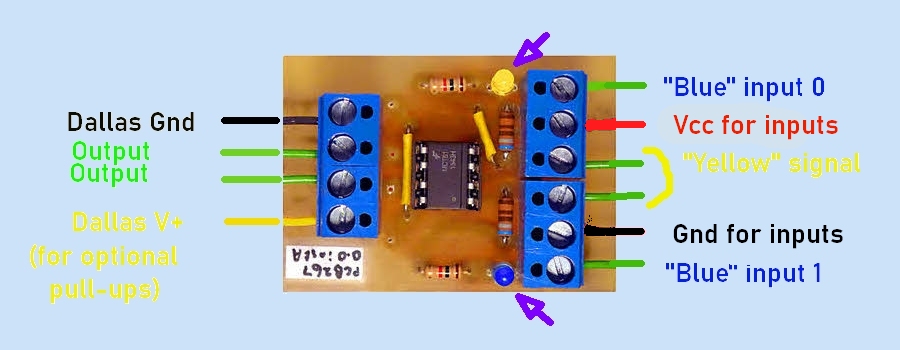
To change the state of either of the board's outputs, SHORT either the two lines labelled "Yellow signal" or "Blue input 0 / Blue input 1". (The two lines in the middle of the six on the right hand (input) side should have been labelled "Yellow" inputs.
When the "Yellow signal" lines are shorted, the yellow LED should light.
When the "Blue" inputs are shorted, the blue LED should light.
Are BOTH sensors "down"... or just one or other? That tells you things!
When either is pair shorted, current will flow through the circuit, powered by whatever you have connected to the "Vcc for inputs" and "Gnd, inputs" terminals. At 13 Sep 26, and for a long time before that, that was 12 volts. "The circuit" includes the LED inside the optoisolator.
At the distal end of the yellow and blue wire pairs, there are reed switches. (A pluviometer is on the wires driving the yellow LED, and a pulse anemometer on the other wires.
13 Sep 26, there was a resistor between the upper "Yellow signal" and "Gnd, Inputs". The opto-isolator chip was and MCT61... and there was just a simple LED inside it. 13 Sep 26, I couldn't see the point of the resistor. Perhaps it was there to prevent something analogous to a floating input... but I don't at 13 Sep 26 see how an LED, a resistor, a switch and a power source can have a "floating input" situation. Surely, the LED goes on if the switch is closed, and doesn't if the switch is open! 13 Sep 26: I disconnected the resistor!
I traced this back to IPS16, a simple wall-wart plugged, via a somewhat complex path!, into the wall strip near the passageway, the one that get power from the generator in power failures.
For Farwatch, wind is monitored by the new(er), expensive anemometer via this PCB267.
From the PCB, the connection to the wind sensor is via cable "B of 13 Aug 14", which is marked at the PCB as being "Direct to sensor". Inspection of the unit on the roof suggests that this is true.
15 Sep 26 (and for a long time before that) the wond readings drive the magenta line of the Farwatch display. (Checked working 15 Sep 26).
From the PCB, the connection to the rain sensor is initially through Cable "A of 22 May 11"
If you found this of interest, please mention in fora, give it a Facebook "like", Google "Plus", or whatever. I've almost given up writing these pages, because it seems they are seldom read, and of course not every reader will use them... so... is there any point? If you want more of this stuff, help!?
Click here to visit my main homepage where you
can explore other areas, such as education, programming, investing.
Page tested for compliance with INDUSTRY (not MS-only) standards, using the free, publicly accessible validator at validator.w3.org. Mostly passes. A few "bad attributes" due to Google+ button, etc.
....... P a g e . . . E n d s .....