The Sparkfun ESP8266 "Thing" (link to Sparkfun product description) has been around for a while now. It is just one of many ways to enjoy the ESP8266 chip.
I like the WiFi. I like the price. I've written more about why I like the Sparkfun ESP8266 "Thing", and how to get started with it.
Many readers will, I suspect, be familiar with the Arduino.
The "ordinary" Arduino has an LED on "D13", on the Arduino's PCB. This can be handy, as many projects need at least one LED to display some status information.
But it also "limits" the wonderful flexibility of the device, by "confusing" the "purity" of the "theoretical" device. In a very small way, and quite worth the price, in my view, but it does.
The designers of many little boards like the Arduino, including the ESP8266 "Thing" choose to "limit" pins in ways like this. Sometimes the limitations are trivial, sometimes not so trivial.
This page is dedicated to describing the "limits" introduced in the design of the Sparkfun ESP8266 "Thing", Dev Board (product WRL-13711). (I hope one day to expand it to include the OTHER Sparkfun "Thing" (product DEV-13907). (In many cases, the same choices were made.)
I'm not an uber expert ESP8266 user... or even an uber expert Arduino user! "Pin" and signal names, as you read about them on the internet give me a BIG HEADACHE.
In what follows, if I say "D5", I mean "the thing" you would affect if you used "setmode(5,OUTPUT);"
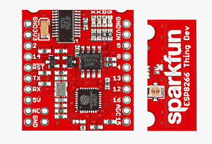
If I say "BrdPin RX", I mean the pin on the Sparkfun ESP8266 "Thing", Dev Board (product WRL-13711), ver at 2/17, that is marked "RX" in the following:
While *I* am not an expert, you can access experts! Sparkfun themselves, of course, have some information of this nature on their site. (I only started this page because I find it a bit scattered and hard to use). There's more, and maybe better, in a arduino.esp8266.com page Sparkfun gives a link to. (That, note, is not specific to the Sparkfun product... I think it is more a "usual plan", which Sparkfun probably mostly followed... but maybe not in every detail?)
Right! Enough! Finally, and not complete...
D2, D14, D7, D8- 2/ 14/ TX/ RX: I really would be careful before using any of these "myself", as ordinary I/O lines, manipulated by one of my programs. I try to avoid using them. They (maybe) can be used... if you know what you are doing. D7 and D8 are used to "talk" to the board when programming it. The set of four may be dedicated to I2C comms... when you need it. (2 and 14 might be available for general I/O when you don't.)
D5- 5: This signal has an LED on it, in the Sparkfun board.
A0- ADC: This is where you connect analog inputs to he board. They should not be more than 1.0 volts.
D16- 16: This behaved a bit strangely when I tried to use it in some early projects. A third party shield PCB labels that line "EN", as in "Chip ENable"... but I suspect that the "EN" label may have been a scrap of a transfer from another project. Though my problems happening to be with that pin may be an indication otherwise. See also note below about "Deep Sleep".
D12, D13, D14, D15/ 12, 13, 14: For SPI signals MISO, MOSI, SCLK (SCL), CS, respectively, pp Sparkfun page. Also from the Sparkfun documentation: "The MISO, MOSI, SCLK, and SPI pins are hard-coded and can't be moved." But, I wonder, if you aren't using SPI, can you use those pins as general, un-"special in any way" I/O lines? (I think you can.) (Were the first to SPI signals named by someone who really hated lysdexics?
The pin marked "/RST": From the Sparkfun page:
Deep Sleep

The ESP8266 has a pretty decent low-power sleep mode- operating
around 70uA. To put the ESP8266 to sleep,
use the ESP.deepSleep(<microseconds>) function.

       ESP.deepSleep(30000000); // Sleep 30 seconds

For it to wake itself back up, the ESP8266 requires an external
connection between pin 16 and its RST pin. Use the handy
"Sleep-EN" jumper to set this connection up.
More quotes (tweaked) from the Sparkfun page...
The ESP8266 should work with any I2C sensor you can throw at it-
just use the Wire library, and the same Wire API calls you're used
to. There are a few differences:

    Pin definition: The ESP2866 doesn't actually have any hardware
    I2C pins- those labeled on the Thing are the default, but you
    can actually use any two pins as SDA and SCL. Calling
    Wire.begin() will assume pins 2 and 14 are SDA and SCL, but
    you can manually set them to any other pin by calling
    Wire.begin([SDA], [SCL]).
For now. Comments, corrections, suggestions for more info that belongs on this page (please say "esp8266-pins.htm"!)... WELCOME!
Please get in touch if you discover flaws in this page. Ways you are using "the Thing" would be of interest, too. Please mention the page's URL. (www. thingie)
If you found this of interest, please mention in fora, give it a Facebook "like", Google "Plus", or whatever. I've almost given up writing these pages, because it seems they are seldom read, and of course not every reader will use them... so... is there any point? If you want more of this stuff, help!?
Click here to visit my main homepage where you
can explore other areas, such as education, programming, investing.
![]() Page tested for compliance with INDUSTRY (not MS-only) standards, using the free, publicly accessible validator at validator.w3.org. Mostly passes. A few "bad attributes" due to Google+ button, etc.
Page tested for compliance with INDUSTRY (not MS-only) standards, using the free, publicly accessible validator at validator.w3.org. Mostly passes. A few "bad attributes" due to Google+ button, etc.
....... P a g e . . . E n d s .....