The Sparkfun ESP8266 "Thing" has been around for a while now. It is just one of many ways to enjoy the ESP8266 chip.
The "Thing" has one dedicated analog input pin. Nota Bene: It should not be subjected to more than 1.0v... at least in the Sparkfun 8266 based "Thing" board... but I suspect the limitation is common to many 8266 boards. This page is about that. It is a sub-page, off of another page I've prepared for you, which speaks about ESP 8266 Things more generally.
Put the following in your program...
analogRead(A0)
... and it will return 0 to 1023, depending upon the voltage present on the pin labeled "ADC".
That's "it", experts. You now know "all about" the Thing's analog input. Just before you go....
My first success with my own remote sensing and control across the internet was with my Arduserver.
It is a simple demo package, now implemented on a variety of platforms. It lets you turn an LED on or off, and lets you "see" that you were successful by the LED's effect upon a light sensor, also connected to the Arduserver.
The "Thing" is a little depressing, because with a Thing, anyone can get an Arduserver running in about half an hour. It used to be harder!
Just saying. So... "Bye, experts".
The rest of the page is a little help for novices who understand they need to be careful about the 1.0v limit.
If you are a novice, with electronics, the 1.0 volt limit should make a a little nervous... but don't let it scare you away from the analog input all together.
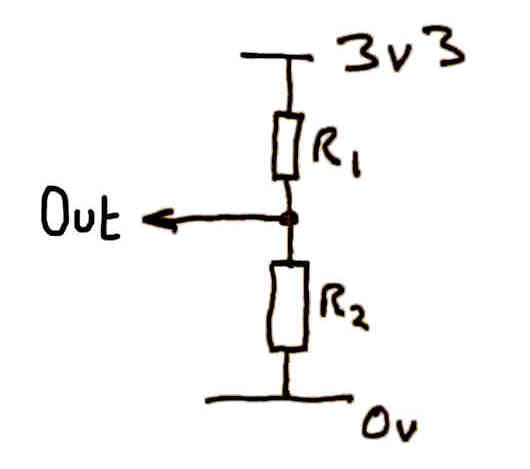
The diagram at the left illustrates a voltage divider.
We can draw from the Thing itself as a source of 3v3... as long as we are not greedy! (We'll come back to that.)
We need the "ground" (or "0v") part of external circuits which are going to be connected to any Thing work that we're doing to be connected to the "ground" ("GND") of the Thing. (This "all the grounds must be connected" fact is one of those "everyone knows" things that people sometimes don't bother to mention. Think about ELECTRONS flowing in CIRCUITS. No way to flow out, around, and back again to where you started, and nothing electrical will "work". So connect grounds.)
The wire marked "Out" is an OUTPUT from what we're doing, which would go INTO the analog input of the Thing. (But don't connect anything yet!)
The analog input of the Thing is between pins 16 and 15, at the upper right of the Thing, as presented at the top of my main page about the Sparkfun ESP8266 Thing. It is marked "ADC", which stands for "Analog to Digital Converter". As long as you don't connect more than 1.0v here, you can measure the voltage "inside" your Thing program...
analogRead(A0)
.. will do. But it is good practice to use "names" for things, so, in the webserver demo from Sparkfun, for instance, early in the program, the line....
const int ANALOG_PIN = A0;
... sets "ANALOG_PIN" up as a "name" for A0. And, in that program, when the programmer wants the Thing to look at the voltage on A0, he/ she says...
analogRead(ANALOG_PIN)
What do you get back? If you say "analogRead(ANALOG_PIN)" when the voltage on that pin is 1.0v, you get 1023 back
voltage 0.5v... you get 512
voltage 0.0v... you get 0
and, in between... in between!
So! Now we know how to READ voltages at the ADC pin. And the webserver demo already has the software we need for some "playing.
Here's another copy of the diagram we had before.
If you hooked that up, and used a 20k resistor for R1 and a 1K resistor for R2, you would be in pretty good shape.
First and foremost, the current flowing from 3v3 to ground through the resistors would not be too large. If you used 20 OHMs and 1 OHM resistors for R1 and R2, at best everything would grind to a halt, and at worst, you would damage the voltage regulator inside your Thing.
The Thing CAN supply SMALL amounts of current for your purposes. I need, soon, to look up what the upper limit is, and keep track of what current demands I am making with my projects. For now, I am just taking it on faith that as long as I have at least 10k between the source of my currents and the ground wires they flow too, the Thing should not be over-stressed.
So... first rule... don't create a path of such low resistance that the current will get high.
Good news! As long as the voltage applied to the ADC pin is not more than 1 volt, the current which will flow in along that circuit is virtually nil, and you don't need to worry about it. (If that were not true, all the calculations would be much more tiresome. As things stand, you just add the resistances R1 and R2, use the voltage which you know is 3V3 (3.3 volts), and apply Mr. Ohms law.... Current will equal the voltage driving the flow divided by the resistance to the flow. The answer will be in amps, if the voltage and resistance were supplied in volts and ohms. If you have, say, 5 volts, and a resistance of 100 ohms, you had better be ready for a 0.05 amp current. (The power supply, for instance, needs to be "good for" 0.05 amp... 50mA. And the wires. A 50mA current would not faze an "ordinary" power supply or wire... but you wouldn't want to ask an Arduino pin to pass that much current. They are delicate. "Good for" up to 20mA... MAX. (It isn't a good idea to operate at 19mA). And "20 mA per pin" isn't the only rule you must keep. Depending on exactly which Arduino you are working with, having 10 pins each carrying 15mA (under the PER PIN limit) would be a bad idea.
So... we've explored the current aspects. Now for the VOLTAGE aspects...
If you had the circuit shown, and R1 was 10k and r2 were 1k, and 3V3 at "the top" of the circuit, the voltage at "output" would be ABOUT 0.33 volts. Electrical engineers talk about "voltage drop". Between the "top" of the circuit, and the bottom, ground, all of the voltage "goes away". In this case, in two stages: Some is "lost" between "the top" and "output". The rest is "lost" between "output" and ground. How much is lost in each stage depends on the resistance of each stage. As the resistance of the upper stage here is ten times the resistance of the lower stage, ten times as much voltage drop will occur across the top stage.
Putting it crudely, but in a form that is perhaps more easily "believed", intuitively, than the formal formulae:
For our circuit, consider there are ELEVEN "parts"... Ten above "output", one below. ALL of the 3V3 will be lost in the whole path. 3.3 divided by 11 is 0.3. SO... between "out" and GROUND, in the bit where 1/11th of the total resistance exists, there will be 0.3 V lost. Between "the top" and "out", all of the rest... 3.0 volts... will be lost.
Remember that a voltage is ALWAYS measured BETWEEN two points. It is "how hard" the electrons "are pushing" to flow between those points. Hook up a circuit like the one described, and measure the voltage between "out" and "the top", and between "out" and "the bottom", ground. You should get values of about 3.0v and of 0.3v. USUALLY, when we say, for instance, "the voltage AT point x" is, say, 2.22 volts, we mean the voltage BETWEEN point x AND GROUND. But voltages are not ALWAYS measured that way.
Earlier, I said that one of the limitations of the ESP8266 is that you must not subject the ADC pin to more than 1.0v. What I was saying is that the voltage BETWEEN the ADC pin AND GROUND should not be greater than 1.0 volt.
Well. Fine. But. If we only ever connect up the circuit we've seen, we don't need the Thing's cleverness to tell us the voltage... we can work it out!
Ah. Yes. But. There are things which CHANGE their resistance in certain circumstances.
Such as a Light Dependant Resistor. (The name pretty well gives the story away.
The one I have here has a resistance of 400K when hidden from ordinary "indoor" lights in my fist, and a resistance of only 900 ohms when 50cm from a 60W incandescent table lamp.
If we JUST put the LDR into our circuit IN PLACE of "R2", we light have a problem.
If the LDR were to become as conductive as a piece of wire, all would be well... the voltage at "Out", called, not very imaginatively, Vout, would be nearly zero. The RATIO of the resistance above and below "out" are what matter to the VOLTAGE remember. (And a 10k R1 would keep the current small enough.)
But what happens if the resistance of the LDR becomes very high. Or even a little high... say 10k? NOT GOOD. The ratio of the resistances would be 1:1, half the total voltage would "drop" ("disappear") across R1, and half across R2... making Vout 1.5 volts... half a volt higher than it should be. And, yes, half a volt IS TOO MUCH.
What to do.
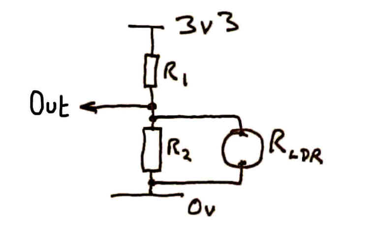
Here's one answer:
It's "messy". It has its flaws. But if R1 is 33k (a strange number in "the real world", but a "normal" resistor size in the electronics world), and R2 is 10k , then with no LDR, Vout is 0.7 volts. (That can be calculated, by some not very complicated mathematical rules, or more simply determined just by hooking up some resistors and 3V3.
So... less than 1v. Good!
And what happens when we connect the LDR alongside ("in parallel with", as in the diagram) R2?....
Think, before you read the answer. What we care MOST about is that we don't want Vout going above 1.0 volt. 33k and 10k on their own produced 0.7 volts between "Out" and Ground. What change will arise if we provide another path for the electricity, parallel to R2? This about the extremes. We already know the answer when the LDR is "extremely resistant". That gives 0.7v because an extremely resistant LDR is like an ABSENT LDR. And it the LDR becomes very CONDUCTIVE? (It becomes more conductive as light levels rise.) Remember the voltage drops were proportional to the resistances. LESS resistance down below, and there will be less voltage drop down below. But ALL of the voltage must be "dropped", so less below, means more above.... sooo.....
Spoiler alert!
I'm about to tell you if the new circuit is okay!
========
Yes! It is okay! An LDR would never have NO resistance, but, consider the extreme. What if it did? Vout would fall to ZERO!
Our little circuit is crude.
But whatever you may say about it, even people with a limited theoretical understanding of electronics can be helped to see that at least we won't be damaging our "Thing" with the circuit.
I've... used?... another day churning this out. Most of the light falling on the sensor is from the desk lamp here beside me as I type.
First tests were an abject failure... analogRead() returned values between 750 and 770 with the LDR under a desk lamp, in the shade of my hand... and even when the LDR was Just Missing.
A bit of thinking made me realize I hadn't hooked it up according to the plan we'd hatched.
As soon as I did... and remember: The resistor values were chosen "at random" (well, not quite), to suit the resistors in my junk box. The LDR was "chosen" in the same manner. It was what I had. NOW the software... the basic "web page server" example, using the "/read" command, reports:
26: When lamp (60W) about 5cm from sensor (LDR) (Don't leave it like that for long. I don't think the sensor will do well at the heat which will arise.)
35: Lamp 15cm from sensor.
61: Lamp 30cm from sensor.
673: Sensor "hidden" from light by cupped hand : 726: Sensor "hidden" from light by inverted tea mug. (Gak. The sacrifices I make for you. I really should have drunk that tea while it was at least warm.)
761: Sensor taken out of circuit.
Some may scorn those values! And a "fancier" circuit would have its merits. BUT! Even with that CRUDE circuit, I think we have a very creditable light sensor, more than adequate for SOME applications.
For instance: I came to the ESP8266 "Thing" a long time after creating my "Arduserver", a simple demonstration of controlling digital outputs, and reading analog and digital sensors across the internet. With the little sensor we've built up in the course of this, we have a perfectly adequate Arduserver with (almost) nothing more than the "demo" web-server that is in Sparkfun's excellent support materials for the Thing.
They've already provided an LED, on board, which can be turned on and off via a web browser, across the web. If you hook up an LDR, as described above, and bend it 'round to "look" at the LED, even with the distraction of the nearby "power" LED, you can "see" the effect of turning the on-board LED on and off:
Analog pin reading, LED off: 41-44, depending on where table lamp is shining...
Analog pin reading, LED on: 34 or 35... WORKS!... and that's "first try", without refining any of many things which could BE refined, to give a more robust system... External, bigger, isolated LED in place of on-board LED. Sensor and LED isolated together, shielded from extraneous light from rest of world... tin foil works well, once all exposed metal isolated with electrical tape.
Please get in touch if you discover flaws in this page. Ways you are using "the Thing" would be of interest, too. Please mention the page's URL. (www. thingie)
If you found this of interest, please mention in fora, give it a Facebook "like", Google "Plus", or whatever. I've almost given up writing these pages, because it seems they are seldom read, and of course not every reader will use them... so... is there any point? If you want more of this stuff, help!?
Click here to visit my main homepage where you
can explore other areas, such as education, programming, investing.
![]() Page tested for compliance with INDUSTRY (not MS-only) standards, using the free, publicly accessible validator at validator.w3.org. Mostly passes. A few "bad attributes" due to Google+ button, etc.
Page tested for compliance with INDUSTRY (not MS-only) standards, using the free, publicly accessible validator at validator.w3.org. Mostly passes. A few "bad attributes" due to Google+ button, etc.
....... P a g e . . . E n d s .....