 The opto-coupler needs to be as shown to the right....
The board discussed here is (ver 1.1) available to you from OSH Park. (Cost about $4.50 each, incl p&p, but you have to buy at least 3. If you only want one, contact me about things we can do.)
The board gives you four channels of opto-coupling (also called opto-isolation.)...
An opto-coupler (also known as opto-isolator) is useful for shifting voltage levels. (I.e. turning a digital signal of, say, 12v into a digital signal of a different voltage.. say 5v or 3v3.) It can also be used to provide a "safety barrier" which can pass "safe" digital signals between parts of a system when there is a module you don't entirely trust.
Before we get too carried away, I should mention that if it meets your wants, you could just go out and buy a complete and assembled dual channel opto-isolator from Sparkfun for $6 plus p&p. They also do some level shifting boards. (I discuss one in a page dedicated to the $3 Sparkfun BOB-12009 four channel interface.) Or you can use transistors for level shifting.
Opto-isolators are a very robust "answer". I particulary like to use them when something is on the end of a long wire, e.g. a PIR sensor or an anemometer or a rainfall sensor. WEMPs from lighting striking even as much as a mile away can induce high tranisient voltages in such wires (antennae). With an opto-isolator in a chip in a socket, your worst case scenario is: "Unplug old chip. Insert new."
I made it because I wanted to interface some 12v signals from a PIR "burglar" detector to an Arduino... but it has many uses. Tell me what you would use it for? If you are completely new to opto-couplers, here is a page with a "from scratch" introduction to what a opto-isolator / opto-coupler is good for and how it works.
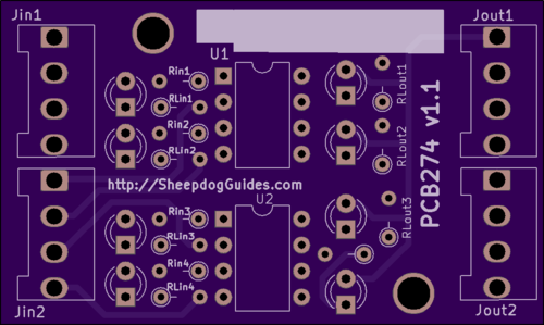
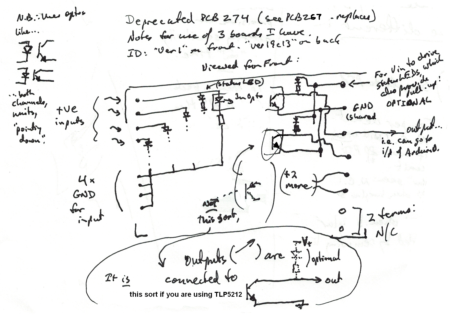
In the image of the PCB, you can see two columns of eight pads, one on the left, one on the right edges of the board. Those pads accept screw terminal blocks, if you wish to use them (3.5mm between pins) (Camden Boss CTB3051 suit... Rapidonline.co.uk stock 21-4707... you'll need FOUR (each 4707 has 4 terminals)).
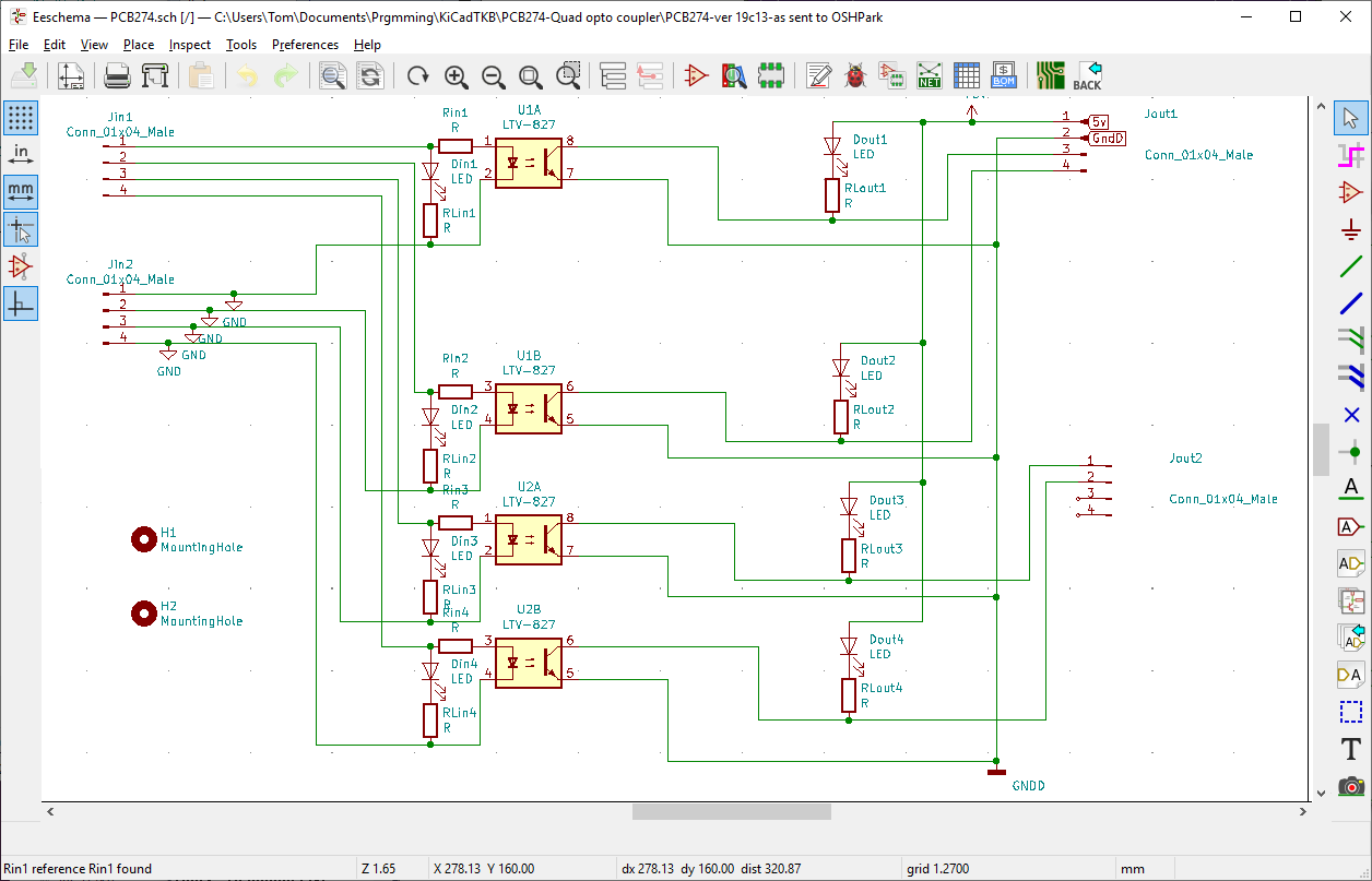
But what signal is on each pin?? If you look at the circuit diagram above, it shows "Jin1","Jin2","Jout1" an "Jout2".
Between them: 16 pads. The pads on the PCB correspond to the pads implied on the circuit diagram, and the layout, as far as that's concerned, is the same. I.e. the pad at the upper right on the PCB is where you supply to the board what is called "5v" on the schematic.
(That "5v" is now called Vcc/Vout on the ver 1.1 circuit diagram. It can be whatever you need. If you are connecting the outputs of PCB274 to a 3v3 Arduino, you would use 3v3 for Vout (and calculate the resistor values for RLout1-4 accordingly.) "Vout" is meant to imply "the voltage for the "output" side of the board, NOT that a voltage "comes out" via this pad. It doesn't. You "send" voltage "in" via the pad... if you are using the LEDs on the outputs from the optocouplers, or if you want to pull the lines up. (The LED/resistor pair create quite a strong pull up. If you want a weak pull up, and don't mind sacrificing the LED, just put 10k (say) "across" the part of the circuit where the LED/resistor would go. (And supply Vout.)))
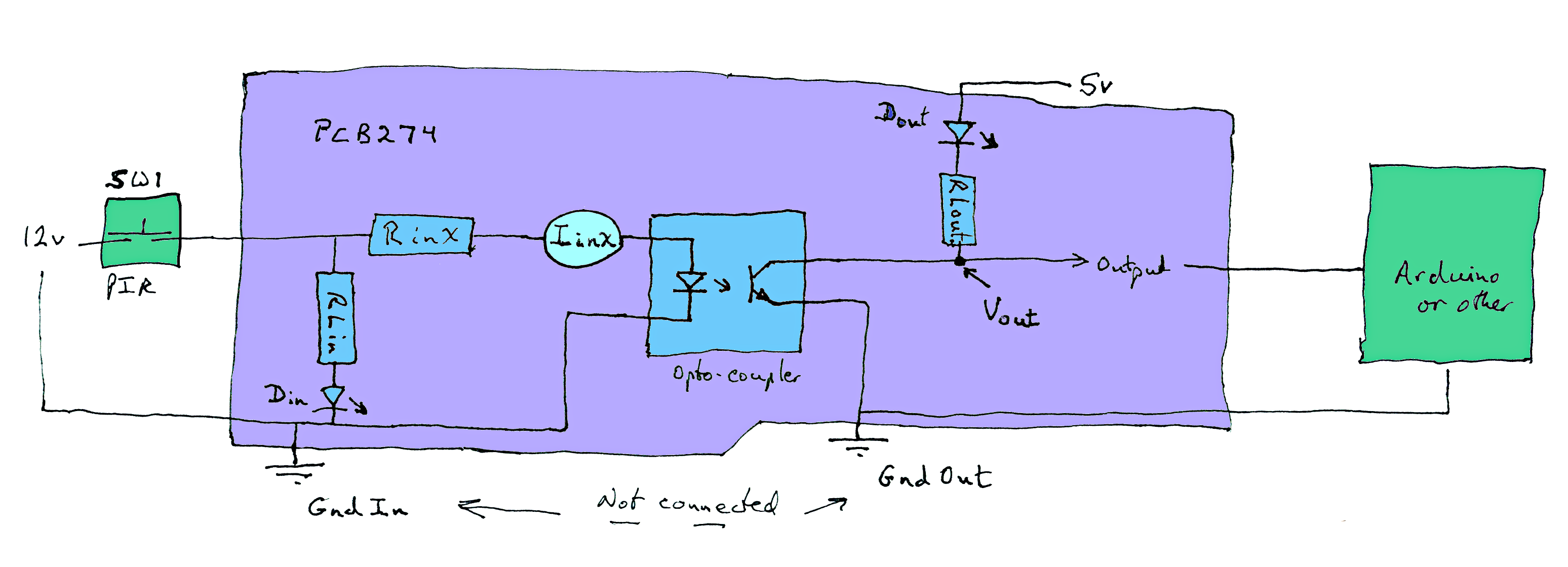
The following is one channel. On the left I've drawn the PIR as a simple momentary switch. On the right you have the Arduino. Everything between the green boxes (left and right) is what is on my PCB, which I call "PCB275". Suggested values for resistors to come.
---- PIR switch NOT closed, output from PCB: zero volts.
---- PIR switch closed: Volts into PCB: 12. Volts out: 5.
Read, mark, learn: There are two, separate "grounds" on this PCB. Well, there would be, wouldn't there, if you wanted to isolate two parts of a bigger system?
There's no general rule about having one ground in a circuit, even if different parts operate at different voltages. But on this PCB, things have been taken a step further, and the two halves of the circuit are COMPLETELY separate.
You will need to remember this when using a voltmeter. It will be no use, for instance, putting the tip of your voltmeter probe on the trace between Din1 and RLin1 if the other wire from your voltmeter is connected to something on the output side of the circuit... and unless you have a good voltmeter (very high impendence), it could cause problems!
To make this PCB do something, you only need:
You don't even need the 5v into the board via Jout1-1.
You would connect two wires to the input side. (Left side, in diagrams.) And two wires to the output side.
---------
The discrete LEDs and their resistors are only there to give you visible indications of the states of various lines. .
---------
If you supply two opto-isolator chips, and four resistors, you can pass four independent data channels through the board.
If you include DoutX+RLoutX in your instance of the board, they also provide a pull-up on the output. (I'm not 100% confident that putting this LED in the circuit is without some downsides, by the way. It makes it harder for the transistor in Ux to make the output low... but with the components I used, all seemed to "work".)
---------
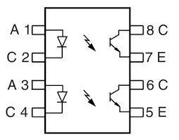
The opto-coupler needs to be as shown to the right....
... i.e. a standard 8pin DIL component. (0.1" between pins, 0.3" between columns of pins.) Note in particular that in this opto-coupler ALL of the current flows are from the "top" of the chip to the bottom. (In some chips, one or the other of either/or the LEDs or transistors "point" the other way.)
I used an Isocom TLP521-2. (Note that using a different opto-isolator may mean that values needed for various resistors, and the current, voltages it can handle may be different.
---------
Voltage levels, LEDs, resistors: I doubt you will want exactly the same components in your PCB as I wanted mine.
I was working with a 12v input signal. If your voltage is different, that will have implications for your choice for RinX and RLinX.
A word about the component names. There are four channels. The resistors limiting the current through the LED inside the opto-couplers are called Rin1, Rin2, Rin3 and Rin4. If I want to say "one of those resistors", I will say RinX. Note that there is a set called RinX and also a set called RLinX. ("L" for "the resistor that goes with the discrete LED".)
There are two sets of (optional) discrete LEDs: DinX and DoutX. The circuit diagram shows FOUR opto-isolator modules, but there are only TWO opto-isolator chips on the PCB. That is because each chip holds two opto-isolator modules. The symbols on the circuit diagram speak of U1A and U1B. Those are the modules in the first chip, chip "U1". The pin numbers are also given on the circuit diagram.
I used some small red LEDs which came from my junk box. (They gave a 1.8v drop.) Your choice of LED, and your wishes as to how bright they should be will affect what is the right value for the associated resistors. Be careful about how much current you ask other parts of the circuit to carry.
It is quite easy, if you make mistakes, to "fry" (burn out) the LED inside the opto-coupler. And you won't "see" that it is burned out.
If nothing else is going on, the following will tell you if you've burned out the LED in your opto-coupler. (You must have the channel's Rin installed as part of "nothing else going on"!)
Apply your normal "on" voltage to the board's input for the channel in question. Connect one side of your voltmeter to the ground (zero volts) for the input side of your circuit. Connect the other to the "high" pin of the opto-isolator's LED. (The pin for the side of the LED that it's arrow does not point to.) The voltage should be much less than the voltage of your input signal. If your LED is blown, there will be no current flowing through RinX, so no voltage drop, so you will see the full input signal voltage on the voltmeter.
I didn't care about the current demands on my input signal, and used 1k resistor for RLinX. Using 4k7 for RinX only subjected the LED in the opto-coupler to 2.5mA. (IinX, in the sketch... the circular element is meant to show an ammeter.) That opto-coupler is rated to allow 50mA MAX though the LED. (If something is rated 50mA max, it doesn't mean that running it at 45mA is a good idea.). It took that much current to pull the output down to 0.2v when I had DoutX installed, and RLoutXs of 1k. (The current through the opto-coupler's transistor was 2.8mA... which you can get buy subtracting the current into whatever you have "outside" the PCB (a 5v ATMega328 Arduino in my case) from the current at the top of RLOutX.)
I've done a simple little Arduino program you may find useful for testing your board. And a page describing the little Arduino program for monitoring the state of some inputs to the Arduino. (You would connect the outputs of PCB274 to inputs on the Arduino running that program.)
I'm sorry these are scruffy, but there are only so many hours in the day...
You are responsible for any consequences of using what is on any of my pages!
I am not aware of flaws in the board, but it hasn't been around very long. And, more especially, I can't know what connections you are going to make, can I?
Please get in touch if you discover any flaws in the board, or any ways to go wrong. How are using it would also be of interest. Cite "PCB274", please.
I would welcome news of any use you put the PCB to... especially if it comes with a photo, and permission to mention here. By all means give me with that any website, blog, etc, you want publicity for.
If you found this of interest, please mention in fora, give it a Facebook "like", or whatever. I've almost given up writing these pages, because it seems they are seldom read, and of course not every reader will use them... so... is there any point? If you want more of this stuff, help!?
To search THIS site.... (Go to my other sites, below, and use their search buttons if you want to search them.)
|
|||
| search engine by freefind |
Click here to visit my main homepage where you can explore other areas, such as education, programming, investing.
To email this page's editor, Tom Boyd.... Editor's email address. Suggestions welcomed! Please cite "PCB274-quad-opto-coupler.htm".
![]() Page has been tested for compliance with INDUSTRY (not MS-only) standards, using the free, publicly accessible validator at validator.w3.org. Mostly passes, unless there are some instances of pre-HTML5 element alignment lingering.
Page has been tested for compliance with INDUSTRY (not MS-only) standards, using the free, publicly accessible validator at validator.w3.org. Mostly passes, unless there are some instances of pre-HTML5 element alignment lingering.
AND passes...

....... P a g e . . . E n d s .....