This is not yet a "product" that you can buy. This page is for the use of a small group of developers, working to make the board into something you can buy! See project's main page for mailing list information, but also further caveats, if you are not already familiar with them.
This page starts with some general information about the DCDW boards, and then turns to details relating to the boards in different configurations, as achieved by component selection and the making or breaking of links and tracks. (There's also a small section at the bottom discussing deprecated designs.)
In the early days of the project, a very few version 0.1 boards were made. If you have one of those, you are largely on your own, apart from the little bit of "Deprecated designs" stuff at the bottom. (But save it... imagine if you had an Apple I PCB today!) You can achieve most of the circuits discussed as "vers 0.2" with a 0.1 board... you just have to work harder!
And now... November 2011... the Version 0.2 boards are "old", and we have, ta! da!... Version 1.0...
Here are some configurations of the version 0.2 board, in detail. See note below "===".. it applies to all.
Shows the user parts to configure the three oscillators A, B, C, where Osc C switches the TX data between A and B. One, two or all three oscillators may use an R or C that is a sensor.
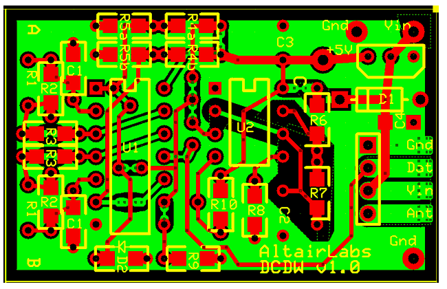
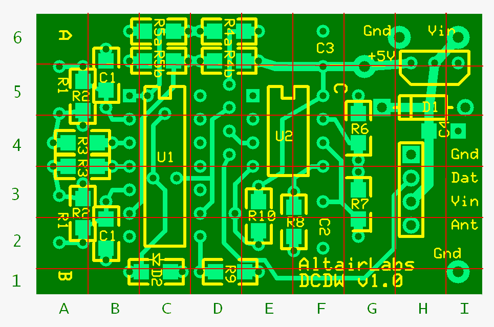
The top diagram is nicely done, showing you linkages and components... but on a v.0.2 board. Below it is a version 1.0 board, so it is easy for you to work out what you have to do to achieve the old circuit on the new board.
A Two-Button Remote is created by cutting the control inputs for Osc A and B and operating them instead by two push buttons working against two pull-down resistors. Osc C may be left unpopulated.
The top diagram is nicely done, showing you linkages and components... but on a v.0.2 board. Below it is a version 1.0 board, so it is easy for you to work out what you have to do to achieve the old circuit on the new board.
Same trace cuts as Two-Button, except Normally Closed alarm loops are wired in place of the pull-down resistors and pull-up resistors are put where the Two-Button switches were. Now the A or B tone will activate when the corresponding alarm loop is broken.
Single channel precision humidity sensor. Oscillator C is configured to temperature compensate a sensor like Humirel, Osc A and B are not used and need not be populated. The left half of the board may be chopped off. (Humidity sensors are expensive... so however cheap the rest of the device can be made, a humidity sensing circuit will always be expensive. Sigh.)
The top diagram is nicely done, showing you linkages and components... but on a v.0.2 board. Below it is a version 1.0 board, so it is easy for you to work out what you have to do to achieve the old circuit on the new board.
One sensor is reported to the single receiver with a frequency, as usual. The other channel is used for an "Identity Tone", sent every so often, to identify the module reporting. Osc C controls how often a message is sent. In between transmissions, power consumption is greatly reduced to extend battery life. Many similar sensors may be deployed on the same RF channel and read by one receiver.
The top diagram is nicely done, showing you linkages and components... but on a v.0.2 board. Below it is a version 1.0 board, so it is easy for you to work out what you have to do to achieve the old circuit on the new board.
===================
In all modes Osc A and B provide for "swamping resistors" that can compress photo-resistor sensor outputs into a range that can be handled by an RF link and Arduino. (Think of changing the brightness and contrast in a photograph.)
Many combinations and variations on the schemes above are possible. For instance DCDW02SensorWithIdentAndBatterySaver can be used to monitor switches or alarm loops that are connected into the extra component traces of Osc A or B.
For example: By connecting a number of switches with R/2R ladder network it should be possible for one DCDW to monitor N independent switches, while still having the second channel free for that DCDW's unique Ident Tone. N could easily be 4, maybe as high as 6 with sufficiently clever software.
Schematic- v0.2
Schematic- v0.2 buttons
Schematic- v0.2 BA